
| Integrated application resource: Mechanical features | ISO 10303-113:2021(E) © ISO |
The counterbore_countersink_schema provides resources for the representations of parametric data sets used to specify properties for those elements. It provides specific support for instantiating the parametric data as content in a piece part definition or as content in an assembly definition.
This clause defines the information requirements to which implementations shall conform using the EXPRESS language as defined in ISO 10303-11. The following EXPRESS declaration begins the counterbore_countersink_schema and identifies the necessary external references.Each implementation of an AP that uses this schema and that encodes entity names shall use the encoding specified in Annex A. Each reference to this schema in an open system shall use the identifier encoding specified in Annex B. This schema is illustrated in Annex D using the EXPRESS-G notation.
EXPRESS specification:
         *)

            	SCHEMA counterbore_countersink_schema;
            REFERENCE FROM
            geometry_schema

               --
            ISO 10303-42
  (axis2_placement_3d);
            REFERENCE FROM
            machining_feature_schema

               --
            ISO 10303-113
  (composite_hole,


            round_hole);
            REFERENCE FROM
            measure_schema

               --
            ISO 10303-41
  (length_measure_with_unit,


            plane_angle_measure_with_unit,


            positive_length_measure_with_unit,


            positive_plane_angle_measure_with_unit);
            REFERENCE FROM
            product_definition_schema

               --
            ISO 10303-41
  (product_definition);
            REFERENCE FROM
            product_property_definition_schema

               --
            ISO 10303-41
  (characterized_object,


            property_definition,


            shape_aspect,


            shape_aspect_occurrence);
            REFERENCE FROM
            product_property_representation_schema

               --
            ISO 10303-41
  (item_identified_representation_usage,


            item_identified_representation_usage_definition,


            shape_representation);
            REFERENCE FROM
            product_structure_schema

               --
            ISO 10303-44
  (multi_level_reference_designator);
            REFERENCE FROM
            representation_schema

               --
            ISO 10303-43
  (representation);
            REFERENCE FROM
            shape_tolerance_schema

               --
            ISO 10303-47
  (limits_and_fits,


            tolerance_value);

(*
NOTE 1 The schemas referenced above are specified in the following parts:
geometry_schema ISO 10303-42 machining_feature_schema ISO 10303-113 measure_schema ISO 10303-41 product_definition_schema ISO 10303-41 product_property_definition_schema ISO 10303-41 product_property_representation_schema ISO 10303-41 product_structure_schema ISO 10303-44 representation_schema ISO 10303-43 shape_tolerance_schema ISO 10303-47
NOTE 2 See Annex D for a graphical representation of this schema.
Important concepts for this schema are basic_round_hole, explicit_round_hole and explicit_composite_hole. The basic_round_hole and explicit_round_hole are subtypes of round_hole declared in the machining_feature_schema. The explicit_composite_hole is a subtype of composite_hole declared in the machining_feature_schema. The explicit subtypes capture in a compact model, domain specific parametric data values that have high rates of application in industrial usage.
The explicit_round_hole and explicit_composite_hole entities are extended in further subtypes counterbore_hole_definition, countersink_hole_definition, counterdrill_hole_definition, spotface_definition, and spotface_hole_definition to form a set of parametric template definitions. For general design applications, explicit geometry may be associated with those definitions.
To further optimize product data exchange and sharing, additional subtypes simplified_counterbore_hole_definition, simplified_countersink_hole_definition, simplified_spotface_hole_definition, and simplified_counterdrill_hole_definition are provided that eliminate support for explicit geometry and only provide location and orientation information.
In a piece part design context, the application of the above definitions would be accomplished by populating basic_round_hole_occurrence, counterbore_hole_occurrence, countersink_hole_occurrence, counterdrill_hole_occurrence, or spotface_occurrence, each of which is a subtype of shape_aspect_occurrence.
In an assembly design context, the application of the above definitions would use the further subtypes basic_round_hole_occurrence_in_assembly, counterbore_hole_occurrence_in_assembly, countersink_hole_occurrence_in_assembly, counterdrill_hole_occurrence_in_assembly, or spotface_occurrence_in_assembly. The assembly design context entities provide for specification of the list of components in the assembly that are being modified by the application of the hole definitions. The location of the starting point for the modification is on a surface of the first member of the list.
The following table describes use cases and essential elements to be provided for each use case.
Table 1 — Illustration of use case applications of entities in this schema
A brief discussion of application of entities defined in this schema to an assembly scenario is provided in Annex E.
EXPRESS specification:
            *)

            TYPE
            ccs_item_identified_representation_usage_definition
            =


            SELECT
            BASED_ON
            item_identified_representation_usage_definition
            WITH


               (characterized_object);

            END_TYPE;

            (*
EXPRESS specification:
            *)

            TYPE
            tolerance_value_or_limits_and_fits
            =


            SELECT

               (tolerance_value,
    limits_and_fits);

            END_TYPE;

            (*
EXPRESS specification:
            *)

            ENTITY basic_round_hole

              SUBTYPE OF (round_hole);


              depth :
            OPTIONAL
            positive_length_measure_with_unit;


              depth_tolerance :
            OPTIONAL
            tolerance_value;


              diameter : positive_length_measure_with_unit;


              diameter_tolerance :
            OPTIONAL
            tolerance_value_or_limits_and_fits;


              placement : shape_representation;


              through_hole : BOOLEAN;
WHERE

              WR1: SIZEOF(placement\representation.items) = 1;

              WR2: SIZEOF(QUERY( ri <* placement\representation.items |
            ('GEOMETRY_SCHEMA.AXIS2_PLACEMENT_3D' IN TYPEOF (ri))
            )) = 1;

              WR3: 'MEASURE_SCHEMA.LENGTH_MEASURE_WITH_UNIT' IN TYPEOF(depth_tolerance\tolerance_value.lower_bound);

              WR4: 'MEASURE_SCHEMA.LENGTH_MEASURE_WITH_UNIT' IN TYPEOF(depth_tolerance\tolerance_value.upper_bound);

              WR5: NOT('SHAPE_TOLERANCE_SCHEMA.TOLERANCE_VALUE' IN TYPEOF(diameter_tolerance)) OR
            ('MEASURE_SCHEMA.LENGTH_MEASURE_WITH_UNIT' IN TYPEOF(diameter_tolerance\tolerance_value.lower_bound));

              WR6: NOT('SHAPE_TOLERANCE_SCHEMA.TOLERANCE_VALUE' IN TYPEOF(diameter_tolerance)) OR
            ('MEASURE_SCHEMA.LENGTH_MEASURE_WITH_UNIT' IN TYPEOF(diameter_tolerance\tolerance_value.upper_bound));

              WR7: through_hole XOR EXISTS(depth);

            END_ENTITY;
(*
Attribute definitions:
depth: specifies the required hole depth. The value of this attribute need not be specified.
depth_tolerance: specifies the tolerance of the depth. The value of this attribute need not be specified.
diameter: specifies the hole diameter.
diameter_tolerance: specifies the tolerance of the hole diameter. The value of this attribute need not be specified.
placement: specifies a representation that contains as a minimum an axis2_placement_3d that is a placement origin for orientation and position.
through_hole: specifies that the depth of the hole is completely through the item.
Formal propositions:
WR1: Placement shall contain one item.
WR2: One item in the placement shall be an axis2_placement_3d.
WR3: The lower bound of the tolerance shall have a length unit.
WR4: The upper bound of the tolerance shall have a length unit.
WR5: If a tolerance_value is provided for the diameter_tolerance, the lower bound shall have a length unit.
WR6: If a tolerance_value is provided for the diameter_tolerance, the upper bound shall have a length unit.
WR7: The member of basic_round_hole provided shall specify that the hole is drilled completely through the item or it shall specify a depth; a member of basic_round_hole provided shall not specify that the hole is drilled completely through the item and specify a depth.
EXPRESS specification:
            *)

            ENTITY basic_round_hole_occurrence

              SUBTYPE OF (shape_aspect_occurrence);


              SELF\shape_aspect_occurrence.definition : basic_round_hole;
WHERE

              WR1: 'PRODUCT_DEFINITION_SCHEMA.PRODUCT_DEFINITION' IN TYPEOF(SELF\shape_aspect.of_shape\property_definition.definition);

              WR2: SELF\shape_aspect.product_definitional = TRUE;

            END_ENTITY;
(*
Attribute definitions:
definition: specifies the basic_round_hole that provides the parametric data values and geometric reference data values of the basic_round_hole_occurrence.
Formal propositions:
WR1: The basic_round_hole_occurrence shall be associated with a product_definition.
WR2: The basic_round_hole_occurrence shall lie on the physical boundary of the shape that defines the product.
EXPRESS specification:
            *)

            ENTITY basic_round_hole_occurrence_in_assembly

              SUBTYPE OF (basic_round_hole_occurrence);


              modified_components : LIST[1:?] OF
            UNIQUE
            multi_level_reference_designator;

            END_ENTITY;
(*
Attribute definitions:
modified_components: specifies the list of multi_level_reference_designator that provides the components in the assembly that the hole alters.
Informal propositions:
IP1: The placement of the hole shall be on the surface of the first member of modified_components.
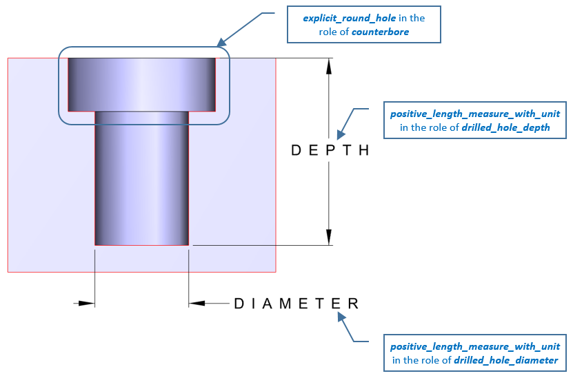
The counterbore_hole_definition is a type of explicit_composite_hole that defines a template structure that provides the parametric requirements for a counterbore hole in a design context. The template includes one or more ordered explicit_round_hole to provide a sequence of bores, and a drilled hole.
NOTE 1 When applicable see ASME Y14.5-2009.
NOTE 2 See Figure 2 for an illustration of the attributes.
NOTE 3 It is assumed that the bore on the far side has the smallest diameter and the bore on the surface side has the largest diameter.
EXPRESS specification:
            *)

            ENTITY counterbore_hole_definition

              SUBTYPE OF (explicit_composite_hole);


              counterbore : LIST[1:?] OF
            UNIQUE
            explicit_round_hole;


              drilled_hole_depth :
            OPTIONAL
            positive_length_measure_with_unit;


              drilled_hole_depth_tolerance :
            OPTIONAL
            tolerance_value;


              drilled_hole_diameter : positive_length_measure_with_unit;


              drilled_hole_diameter_tolerance :
            OPTIONAL
            tolerance_value_or_limits_and_fits;


              through_hole : BOOLEAN;
WHERE

              WR1: through_hole XOR EXISTS(drilled_hole_depth);

              WR2: 'MEASURE_SCHEMA.LENGTH_MEASURE_WITH_UNIT' IN TYPEOF(drilled_hole_depth_tolerance\tolerance_value.lower_bound);

              WR3: 'MEASURE_SCHEMA.LENGTH_MEASURE_WITH_UNIT' IN TYPEOF(drilled_hole_depth_tolerance\tolerance_value.upper_bound);

              WR4: NOT('SHAPE_TOLERANCE_SCHEMA.TOLERANCE_VALUE' IN TYPEOF(drilled_hole_diameter_tolerance)) OR
            ('MEASURE_SCHEMA.LENGTH_MEASURE_WITH_UNIT' IN TYPEOF(drilled_hole_diameter_tolerance\tolerance_value.lower_bound));

              WR5: NOT('SHAPE_TOLERANCE_SCHEMA.TOLERANCE_VALUE' IN TYPEOF(drilled_hole_diameter_tolerance)) OR
            ('MEASURE_SCHEMA.LENGTH_MEASURE_WITH_UNIT' IN TYPEOF(drilled_hole_diameter_tolerance\tolerance_value.upper_bound));

            END_ENTITY;
(*
Attribute definitions:
counterbore: specifies the list of bores that make up a compound counterbore hole, arranged by ascending order of diameter.
drilled_hole_depth: specifies the required hole depth.
drilled_hole_depth_tolerance: specifies the tolerance of the drilled_hole_depth. The tolerance is optional and need not be supplied.
drilled_hole_diameter: specifies the hole diameter.
drilled_hole_diameter_tolerance: specifies the tolerance of the drilled_hole_diameter. The tolerance is optional and need not be supplied.
through_hole: specifies that the drilled hole is required to be completely through the item being drilled.
Formal propositions:
WR1: The member of counterbore_hole_definition provided shall specify that the hole is drilled completely through the item or it shall specify a depth; a member of counterbore_hole_definition provided shall not specify that the hole is drilled completely through the item and specify a depth.
WR2: The lower bound of the tolerance shall have a length unit.
WR3: The upper bound of the tolerance shall have a length unit.
WR4: If a tolerance_value is provided for the drilled_hole_diameter_tolerance, the lower bound shall have a length unit.
WR5: If a tolerance_value is provided for the drilled_hole_diameter_tolerance, the upper bound shall have a length unit.
Informal propositions:
IP1: Counterbore members shall be in ascending order in the list organized according to their drilled_hole_diameter.
IP2: All counterbores shall have a larger diameter than drilled_hole_diameter.
IP3: The axis2_placement_3d in the inherited placement shall define the reference position and orientation for the counterbore_hole_definition.
IP4: The z axis of the axis2_placement_3d shall point into the material of the item being machined.
IP5: The placement of the axis2_placement_3d shall be on the surface of the item being machined.
IP6: The drill axis and each bore axis shall be congruent with the z axis of the placement.
IP7: If a limits_and_fits is provided for the diameter tolerance the limits_and_fits shall be for a hole.
IP8: The counterbore_hole_definition and explicit_round_hole geometry shall be defined in the same context.
EXPRESS specification:
            *)

            ENTITY counterbore_hole_occurrence

              SUBTYPE OF (shape_aspect_occurrence);


              SELF\shape_aspect_occurrence.definition : counterbore_hole_definition;
WHERE

              WR1: 'PRODUCT_DEFINITION_SCHEMA.PRODUCT_DEFINITION' IN TYPEOF(SELF\shape_aspect.of_shape\property_definition.definition);

              WR2: SELF\shape_aspect.product_definitional = TRUE;

            END_ENTITY;
(*
Attribute definitions:
definition: specifies the counterbore_hole_definition that provides the parametric data values and geometric reference data values of the counterbore_hole_occurrence.
Formal propositions:
WR1: The counterbore_hole_occurrence shall be associated with a product_definition.
WR2: A counterbore_hole_occurrence shall specify a member of product_definition_shape with the of_shape attribute.
EXPRESS specification:
            *)

            ENTITY counterbore_hole_occurrence_in_assembly

              SUBTYPE OF (counterbore_hole_occurrence);


              modified_components : LIST[1:?] OF
            UNIQUE
            multi_level_reference_designator;

            END_ENTITY;
(*
Attribute definitions:
modified_components: specifies the list of multi_level_reference_designator that provides the components in the assembly that the hole alters.
Informal propositions:
IP1: The placement of the hole shall be on the surface of the first member of modified_components.
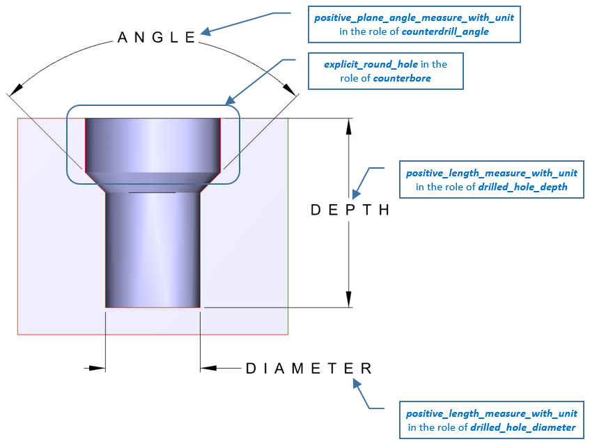
A counterdrill_hole_definition is a type of explicit_composite_hole that defines a template to structure the requirements for a counterdrilled hole.
NOTE 1 When applicable see ASME Y14.5-2009.
NOTE 2 See Figure 3 for an illustration of the attributes.
EXPRESS specification:
            *)

            ENTITY counterdrill_hole_definition

              SUBTYPE OF (explicit_composite_hole);


              counterbore : explicit_round_hole;


              counterdrill_angle : positive_plane_angle_measure_with_unit;


              counterdrill_angle_tolerance :
            OPTIONAL
            tolerance_value;


              drilled_hole_depth :
            OPTIONAL
            positive_length_measure_with_unit;


              drilled_hole_depth_tolerance :
            OPTIONAL
            tolerance_value;


              drilled_hole_diameter : positive_length_measure_with_unit;


              drilled_hole_diameter_tolerance :
            OPTIONAL
            tolerance_value_or_limits_and_fits;


              through_hole : BOOLEAN;
WHERE

              WR1: through_hole XOR EXISTS(drilled_hole_depth);

              WR2: 'MEASURE_SCHEMA.PLANE_ANGLE_MEASURE_WITH_UNIT' IN TYPEOF(counterdrill_angle_tolerance\tolerance_value.lower_bound);

              WR3: 'MEASURE_SCHEMA.PLANE_ANGLE_MEASURE_WITH_UNIT' IN TYPEOF(counterdrill_angle_tolerance\tolerance_value.upper_bound);

              WR4: 'MEASURE_SCHEMA.LENGTH_MEASURE_WITH_UNIT' IN TYPEOF(drilled_hole_depth_tolerance\tolerance_value.lower_bound);

              WR5: 'MEASURE_SCHEMA.LENGTH_MEASURE_WITH_UNIT' IN TYPEOF(drilled_hole_depth_tolerance\tolerance_value.upper_bound);

              WR6: NOT('SHAPE_TOLERANCE_SCHEMA.TOLERANCE_VALUE' IN TYPEOF(drilled_hole_diameter_tolerance)) OR
            ('MEASURE_SCHEMA.LENGTH_MEASURE_WITH_UNIT' IN TYPEOF(drilled_hole_diameter_tolerance\tolerance_value.lower_bound));

              WR7: NOT('SHAPE_TOLERANCE_SCHEMA.TOLERANCE_VALUE' IN TYPEOF(drilled_hole_diameter_tolerance)) OR
            ('MEASURE_SCHEMA.LENGTH_MEASURE_WITH_UNIT' IN TYPEOF(drilled_hole_diameter_tolerance\tolerance_value.upper_bound));

            END_ENTITY;
(*
Attribute definitions:
counterbore: specifies the bore that helps compose a counterdrill_hole_definition.
counterdrill_angle: specifies the required angle for the counterdrill.
counterdrill_angle_tolerance: specifies the tolerance of the counterdrill_angle specification. The tolerance is optional and need not be supplied.
drilled_hole_depth: specifies the required hole depth.
drilled_hole_depth_tolerance: specifies the tolerance of the drill_hole_depth. The tolerance is optional and need not be supplied.
drilled_hole_diameter: specifies the hole diameter.
drilled_hole_diameter_tolerance: specifies the tolerance of the drilled_hole_diameter. The tolerance is optional and need not be supplied.
through_hole: specifies that the depth of the smaller hole is completely through the item.
Formal propositions:
WR1: The member of counterdrill_hole_definition provided shall specify that the hole is drilled completely through the item or it shall specify a depth; a member of counterdrill_hole_definition provided shall not specify that the hole is drilled completely through the item and specify a depth.
WR2: The lower bound of the counterdrill_angle_tolerance shall have a plane angle unit.
WR3: The upper bound of the counterdrill_angle_tolerance shall have a plane angle unit.
WR4: The lower bound of the drilled_hole_depth_tolerance shall have a length unit.
WR5: The upper bound of the drilled_hole_depth_tolerance shall have a length unit.
WR6: If a tolerance_value is provided for the drilled_hole_diameter_tolerance, the lower bound shall have a length unit.
WR7: If a tolerance_value is provided for the drilled_hole_diameter_tolerance, the upper bound shall have a length unit.
Informal propositions:
IP1: The counterbore shall have a larger diameter than the drilled_hole_diameter.
IP2: The axis2_placement_3d in the inherited placement shall define the reference position and orientation for the counterdrill_hole_definition.
IP3: The z axis of the axis2_placement_3d shall point into the material of the item being machined.
IP4: The placement of the axis2_placement_3d shall be on the surface of the item being machined.
IP5: The drill axis and the counterdrill axis and each bore axis shall be congruent with the z axis of the placement.
IP6: The counterdrill_hole_definition and explicit_round_hole geometry shall be defined in the same context.
EXPRESS specification:
            *)

            ENTITY counterdrill_hole_occurrence

              SUBTYPE OF (shape_aspect_occurrence);


              SELF\shape_aspect_occurrence.definition : counterdrill_hole_definition;
WHERE

              WR1: 'PRODUCT_DEFINITION_SCHEMA.PRODUCT_DEFINITION' IN TYPEOF(SELF\shape_aspect.of_shape\property_definition.definition);

              WR2: SELF\shape_aspect.product_definitional = TRUE;

            END_ENTITY;
(*
Attribute definitions:
definition: specifies the counterdrill_hole_definition that provides the parametric data values and geometric reference data values of the counterdrill_hole_occurrence.
Formal propositions:
WR1: The counterdrill_hole_occurrence shall be associated with a product_definition.
WR2: A counterdrill_hole_occurrence shall specify a member of product_definition_shape with the of_shape attribute.
EXPRESS specification:
            *)

            ENTITY counterdrill_hole_occurrence_in_assembly

              SUBTYPE OF (counterdrill_hole_occurrence);


              modified_components : LIST[1:?] OF
            UNIQUE
            multi_level_reference_designator;

            END_ENTITY;
(*
Attribute definitions:
modified_components: specifies the list of multi_level_reference_designator that provides the components in the assembly that the hole alters.
Informal propositions:
IP1: The placement of the hole shall be on the surface of the first member of modified_components.
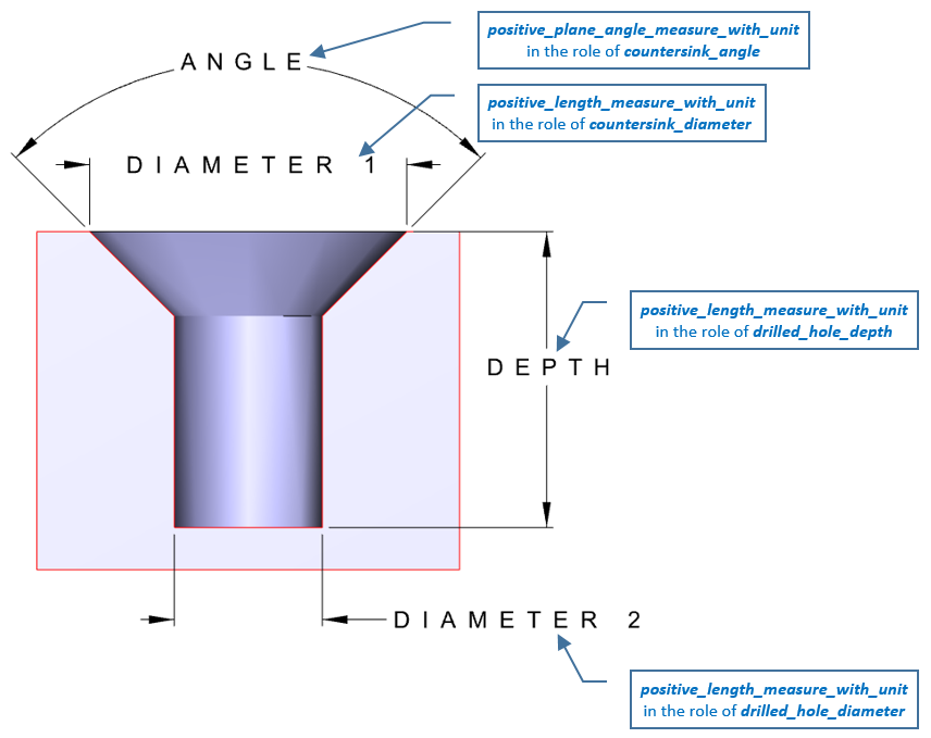
A countersink_hole_definition is a type of explicit_composite_hole that defines a template to structure the requirements for a countersink hole.
NOTE 1 When applicable see ASME Y14.5-2009.
NOTE 2 See Figure 4 for an illustration of the attributes.
EXPRESS specification:
            *)

            ENTITY countersink_hole_definition

              SUBTYPE OF (explicit_composite_hole);


              countersink_angle : positive_plane_angle_measure_with_unit;


              countersink_angle_tolerance :
            OPTIONAL
            tolerance_value;


              countersink_diameter : positive_length_measure_with_unit;


              countersink_diameter_tolerance :
            OPTIONAL
            tolerance_value_or_limits_and_fits;


              drilled_hole_depth :
            OPTIONAL
            positive_length_measure_with_unit;


              drilled_hole_depth_tolerance :
            OPTIONAL
            tolerance_value;


              drilled_hole_diameter : positive_length_measure_with_unit;


              drilled_hole_diameter_tolerance :
            OPTIONAL
            tolerance_value_or_limits_and_fits;


              through_hole : BOOLEAN;
WHERE

              WR1: through_hole XOR EXISTS(drilled_hole_depth);

              WR2: 'MEASURE_SCHEMA.PLANE_ANGLE_MEASURE_WITH_UNIT' IN TYPEOF(countersink_angle_tolerance\tolerance_value.lower_bound);

              WR3: 'MEASURE_SCHEMA.PLANE_ANGLE_MEASURE_WITH_UNIT' IN TYPEOF(countersink_angle_tolerance\tolerance_value.upper_bound);

              WR4: NOT('SHAPE_TOLERANCE_SCHEMA.TOLERANCE_VALUE' IN TYPEOF(countersink_diameter_tolerance)) OR
            ('MEASURE_SCHEMA.LENGTH_MEASURE_WITH_UNIT' IN TYPEOF(countersink_diameter_tolerance\tolerance_value.lower_bound));

              WR5: NOT('SHAPE_TOLERANCE_SCHEMA.TOLERANCE_VALUE' IN TYPEOF(countersink_diameter_tolerance)) OR
            ('MEASURE_SCHEMA.LENGTH_MEASURE_WITH_UNIT' IN TYPEOF(countersink_diameter_tolerance\tolerance_value.upper_bound));

              WR6: 'MEASURE_SCHEMA.LENGTH_MEASURE_WITH_UNIT' IN TYPEOF(drilled_hole_depth_tolerance\tolerance_value.lower_bound);

              WR7: 'MEASURE_SCHEMA.LENGTH_MEASURE_WITH_UNIT' IN TYPEOF(drilled_hole_depth_tolerance\tolerance_value.upper_bound);

              WR8: NOT('SHAPE_TOLERANCE_SCHEMA.TOLERANCE_VALUE' IN TYPEOF(drilled_hole_diameter_tolerance)) OR
            ('MEASURE_SCHEMA.LENGTH_MEASURE_WITH_UNIT' IN TYPEOF(drilled_hole_diameter_tolerance\tolerance_value.lower_bound));

              WR9: NOT('SHAPE_TOLERANCE_SCHEMA.TOLERANCE_VALUE' IN TYPEOF(drilled_hole_diameter_tolerance)) OR
            ('MEASURE_SCHEMA.LENGTH_MEASURE_WITH_UNIT' IN TYPEOF(drilled_hole_diameter_tolerance\tolerance_value.upper_bound));

            END_ENTITY;
(*
Attribute definitions:
countersink_angle: specifies the required angle for the countersink.
countersink_angle_tolerance: specifies the tolerance of the countersink_angle specification. The tolerance is optional and need not be supplied.
countersink_diameter: specifies the required starting diameter of the larger hole on the part surface.
countersink_diameter_tolerance: specifies the tolerance of the countersink_diameter. The tolerance is optional and need not be supplied.
drilled_hole_depth: specifies the required hole depth.
drilled_hole_depth_tolerance: specifies the tolerance of the drilled_hole_depth. The tolerance is optional and need not be supplied.
drilled_hole_diameter: specifies the hole diameter.
drilled_hole_diameter_tolerance: specifies the tolerance of the drilled_hole_diameter. The tolerance is optional and need not be supplied.
through_hole: specifies that the drilled hole is required to be completely through the item being drilled.
Formal propositions:
WR1: The member of countersink_hole_definition provided shall specify that the hole is drilled completely through the item or it shall specify a depth; a member of countersink_hole_definition provided shall not specify that the hole is drilled completely through the item and specify a depth.
WR2: The lower bound of the tolerance shall have a plane angle unit.
WR3: The upper bound of the tolerance shall have a plane angle unit.
WR4: If a tolerance_value is provided for the countersink_diameter_tolerance, the lower bound shall have a length unit.
WR5: If a tolerance_value is provided for the countersink_diameter_tolerance, the upper bound shall have a length unit.
WR6: The lower bound of the tolerance shall have a length unit.
WR7: The upper bound of the tolerance shall have a length unit.
WR8: If a tolerance_value is provided for the drilled_hole_diameter_tolerance, the lower bound shall have a length unit.
WR9: If a tolerance_value is provided for the drilled_hole_diameter_tolerance, the upper bound shall have a length unit.
Informal propositions:
IP1: Countersink_diameter shall have a larger diameter than the drilled_hole_diameter.
IP2: The axis2_placement_3d in the inherited placement shall define the reference position and orientation for the countersink_hole_definition.
IP3: The z axis of the axis2_placement_3d shall point into the material of the item being machined.
IP4: The placement of the axis2_placement_3d shall be on the surface of the item being machined.
IP5: The drill axis and the countersink axis shall be congruent with the z axis of the placement.
IP6: If a limits_and_fits is provided for the diameter tolerance the limits_and_fits shall be for a hole.
IP7: The countersink_hole_definition and explicit_round_hole geometry shall be defined in the same context.
EXPRESS specification:
            *)

            ENTITY countersink_hole_occurrence

              SUBTYPE OF (shape_aspect_occurrence);


              SELF\shape_aspect_occurrence.definition : countersink_hole_definition;
WHERE

              WR1: 'PRODUCT_DEFINITION_SCHEMA.PRODUCT_DEFINITION' IN TYPEOF(SELF\shape_aspect.of_shape\property_definition.definition);

              WR2: SELF\shape_aspect.product_definitional = TRUE;

            END_ENTITY;
(*
Attribute definitions:
definition: specifies the countersink_hole_definition that provides the parametric data values and geometric reference data values of the countersink_hole_occurrence.
Formal propositions:
WR1: The countersink_hole occurrence shall be associated with a product_definition.
WR2: a countersink_hole_occurrence shall specify a member of product_definition_shape with the of_shape attribute.
EXPRESS specification:
            *)

            ENTITY countersink_hole_occurrence_in_assembly

              SUBTYPE OF (countersink_hole_occurrence);


              modified_components : LIST[1:?] OF
            UNIQUE
            multi_level_reference_designator;

            END_ENTITY;
(*
Attribute definitions:
modified_components: specifies the list of multi_level_reference_designator that provides the components in the assembly that the hole alters.
Informal propositions:
IP1: The placement of the hole shall be on the surface of the first member of modified_components.
EXPRESS specification:
            *)

            ENTITY explicit_composite_hole

              SUBTYPE OF (composite_hole);


              placement : shape_representation;
INVERSE

              explicit_shape : SET[0:?] OF item_identified_representation_usage FOR definition;
WHERE

              WR1: SIZEOF(QUERY( ri <* placement\representation.items |
            ('GEOMETRY_SCHEMA.AXIS2_PLACEMENT_3D' IN TYPEOF (ri))
            )) = 1;

              WR2: (SIZEOF(explicit_shape) = 0) OR
            (SIZEOF(QUERY(es <* explicit_shape |
            NOT (placement = es\item_identified_representation_usage.used_representation)
            )) = 0);

            END_ENTITY;
(*
Attribute definitions:
placement: specifies a representation that contains as a minimum an axis2_placement_3d that is a placement origin for orientation and position.
explicit_shape: specifies a set of item_identified_representation_usage , each member of which relates this explicit_composite_hole to a representation and to a representation_item.
Formal propositions:
WR1: One member of placement shall be an axis2_placement_3d.
WR2: The items identified by explicit_shape shall be in the same representation as the placement.
Informal propositions:
IP1: The axis2_placement_3d in the placement shall define the reference position and orientation for the explicit_composite_hole .
IP2: The z axis of the axis2_placement_3d shall point into the material of the item being machined.
IP3: The placement of the axis2_placement_3d shall be on the surface of the item being machined.
IP4: The drill axis and each machining axis shall be congruent with the z axis of the placement.
EXPRESS specification:
            *)

            ENTITY explicit_round_hole

              SUBTYPE OF (round_hole);


              depth : positive_length_measure_with_unit;


              depth_tolerance :
            OPTIONAL
            tolerance_value;


              diameter : positive_length_measure_with_unit;


              diameter_tolerance :
            OPTIONAL
            tolerance_value_or_limits_and_fits;


              placement : shape_representation;
WHERE

              WR1: SIZEOF(QUERY( ri <* placement\representation.items |
            ('GEOMETRY_SCHEMA.AXIS2_PLACEMENT_3D' IN TYPEOF (ri))
            )) = 1;

              WR2: 'MEASURE_SCHEMA.LENGTH_MEASURE_WITH_UNIT' IN TYPEOF(depth_tolerance\tolerance_value.lower_bound);

              WR3: 'MEASURE_SCHEMA.LENGTH_MEASURE_WITH_UNIT' IN TYPEOF(depth_tolerance\tolerance_value.upper_bound);

              WR4: NOT('SHAPE_TOLERANCE_SCHEMA.TOLERANCE_VALUE' IN TYPEOF(diameter_tolerance)) OR
            ('MEASURE_SCHEMA.LENGTH_MEASURE_WITH_UNIT' IN TYPEOF(diameter_tolerance\tolerance_value.lower_bound));

              WR5: NOT('SHAPE_TOLERANCE_SCHEMA.TOLERANCE_VALUE' IN TYPEOF(diameter_tolerance)) OR
            ('MEASURE_SCHEMA.LENGTH_MEASURE_WITH_UNIT' IN TYPEOF(diameter_tolerance\tolerance_value.upper_bound));

            END_ENTITY;
(*
Attribute definitions:
depth: specifies the required hole depth.
depth_tolerance: specifies the tolerance of the depth. The tolerance is optional and need not be supplied.
diameter: specifies the hole diameter.
diameter_tolerance: specifies the tolerance of the hole diameter. The tolerance is optional and need not be supplied.
placement: specifies a representation that contains as a minimum an axis2_placement_3d that is a placement origin for orientation and position.
Formal propositions:
WR1: One item in the placement shall be an axis2_placement_3d.
WR2: The lower bound of the tolerance shall have a length unit.
WR3: The upper bound of the tolerance shall have a length unit.
WR4: If a tolerance_value is provided for the diameter_tolerance, the lower bound shall have a length unit.
WR5: If a tolerance_value is provided for the diameter_tolerance, the upper bound shall have a length unit.
Informal propositions:
IP1: Counterbore members shall be in ascending order in the list organized according to their drilled_hole_diameter.
IP2: Counterbore[1] shall have a larger diameter than drilled_hole_diameter.
IP3: The axis2_placement_3d in the inherited placement shall define the reference position and orientation for the counterbore_hole_definition.
IP4: The z axis of the axis2_placement_3d shall point into the material of the item being machined.
IP5: The placement of the axis2_placement_3d shall be on the surface of the item being machined.
IP6: The drill axis and each bore axis shall be congruent with the z axis of the placement.
IP7: If a limits_and_fits is provided for the diameter tolerance, the limits_and_fits shall be for a hole.
IP8: Counterbore_hole_definition and explicit_round_hole geometry shall be defined in the same context.
EXPRESS specification:
            *)

            ENTITY simplified_counterbore_hole_definition

              SUBTYPE OF (counterbore_hole_definition);
WHERE

              WR1: SIZEOF(SELF\explicit_composite_hole.placement\representation.items) = 1;

            END_ENTITY;
(*
Formal propositions:
WR1: There shall be exactly one item in the representation.
EXPRESS specification:
            *)

            ENTITY simplified_counterdrill_hole_definition

              SUBTYPE OF (counterdrill_hole_definition);
WHERE

              WR1: SIZEOF(SELF\explicit_composite_hole.placement\representation.items) = 1;

            END_ENTITY;
(*
Formal propositions:
WR1: There shall be exactly one item in the representation.
EXPRESS specification:
            *)

            ENTITY simplified_countersink_hole_definition

              SUBTYPE OF (countersink_hole_definition);
WHERE

              WR1: SIZEOF(SELF\explicit_composite_hole.placement\representation.items) = 1;

            END_ENTITY;
(*
Formal propositions:
WR1: There shall be exactly one item in the representation.
EXPRESS specification:
            *)

            ENTITY simplified_spotface_hole_definition

              SUBTYPE OF (spotface_hole_definition, simplified_counterbore_hole_definition);

            END_ENTITY;
(*
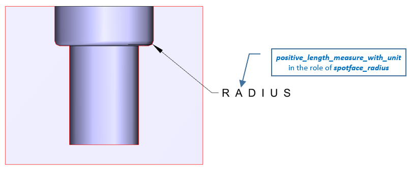
A spotface_definition is a type of explicit_round_hole in which a radius is applied to the bottom surface of the outside diameter.
NOTE 1 When applicable see ASME Y14.5-2009.
NOTE 2 See Figure 5 for an illustration of the attributes.
EXPRESS specification:
            *)

            ENTITY spotface_definition

              SUBTYPE OF (explicit_round_hole);


              spotface_radius : positive_length_measure_with_unit;


              spotface_radius_tolerance :
            OPTIONAL
            tolerance_value;
WHERE

              WR1: 'MEASURE_SCHEMA.LENGTH_MEASURE_WITH_UNIT' IN TYPEOF(spotface_radius_tolerance\tolerance_value.lower_bound);

              WR2: 'MEASURE_SCHEMA.LENGTH_MEASURE_WITH_UNIT' IN TYPEOF(spotface_radius_tolerance\tolerance_value.upper_bound);

            END_ENTITY;
(*
Attribute definitions:
spotface_radius: specifies the required fillet radius on the bottom of the larger hole.
spotface_radius_tolerance: specifies the tolerance of the specified fillet radius. The tolerance is optional and need not be supplied.
Formal propositions:
WR1: The lower bound of the spotface_radius_tolerance shall have a length unit.
WR2: The upper bound of the spotface_radius_tolerance shall have a length unit.
A spotface_hole_definition is a type of counterbore_hole_definition in which a radius is applied to the bottom surface of each bore.
NOTE When applicable see ASME Y14.5-2009.
EXPRESS specification:
            *)

            ENTITY spotface_hole_definition

              SUBTYPE OF (counterbore_hole_definition);


              SELF\counterbore_hole_definition.counterbore RENAMED spotface : LIST[1:?] OF
            UNIQUE
            spotface_definition;

            END_ENTITY;
(*
Attribute definitions:
spotface: specifies the list of bores that make up a compound spotface hole, arranged by ascending order of diameter.
EXPRESS specification:
            *)

            ENTITY spotface_occurrence

              SUBTYPE OF (counterbore_hole_occurrence);


              SELF\counterbore_hole_occurrence.definition : spotface_hole_definition;

            END_ENTITY;
(*
Attribute definitions:
definition: specifies the spotface_hole_definition that provides the parametric data values and geometric reference data values of the spotface_occurrence.
EXPRESS specification:
            *)

            ENTITY spotface_occurrence_in_assembly

              SUBTYPE OF (counterbore_hole_occurrence_in_assembly);


              SELF\counterbore_hole_occurrence.definition : spotface_hole_definition;

            END_ENTITY;
(*
Attribute definitions:
definition: specifies the spotface_hole_definition that provides the parametric data values and geometric reference data values of the spotface_occurrence_in_assembly.
The round_hole_subtypes constraint specifies a constraint that applies to instances of subtypes of round_hole.
EXPRESS specification:
            *)
SUBTYPE_CONSTRAINT round_hole_subtypes FOR round_hole;

              ONEOF (basic_round_hole,
         explicit_round_hole);

            END_SUBTYPE_CONSTRAINT;
(*
         *)

         END_SCHEMA;  -- counterbore_countersink_schema
(*
© ISO 2021 — All rights reserved