Feed and Speed Optimization
The intent is to show how AP-238 supports the refinement of nominal machining process plans to generate optimized process plans given better information just prior to machining. Extensions to the technological parameters are proposed to handle the cutter cross sectional area. One aspect of the demonstration is to validate these proposed extensions.
- We start with an AP-238 program for 3-axis roughing of the Airbus fish head part. There will be three versions of this, at least: Sandvik's large tool, NIST's small tool, Boeing's medium-sized tool. The AP-238 program will have resulted from one of those sites exporting AP-238 from their CAM system.
- >The AP-238 is run through the STEP-NC Explorer to generate NC code for the target machine. Additionally, a STEP AP-203 or STL file is exported for the starting stock.
- The NC code and STEP or STL file are loaded into Vericut for a machining simulation. Vericut outputs a sequence of cutter contact profiles as per the "Digitized Cross-Sectional Area" slide in Leon Xu's presentation.
- The Vericut output is loaded into a custom Boeing application that calculates a series of six cross-sectional area parameters for each NC code line. The result is a CSV file.
- The CSV file is loaded into a (new) STEP merge process, which associates the NC code line with the AP-238 toolpath, and inserts the tsix cross-sectional area parameters into proposed extensions to the technological parameters. An enhanced AP-238 program results.
- Just prior to cutting, the enhanced AP-238 program is run through the STEP-NC Explorer to generate NC code. The Explorer calls some Boeing optimization algorithms that compute feeds and speeds based on requirements such as minimize cutting time or maximize tool life. The result is an NC code program optimized for the specific requirement.
Associated Files
- Optimization Presentation [pdf, 430k]
- Cross-Section Parameters [ppt, 660k]
- Cutter Params used for Optimization [ppt, 76k]
- Sweden_override_20080109_opt_const_chip1.238 [stepnc, 2M]
fishhead test part, showing the associated tolerances.
Tool information for fishhead test part, showing tool parameters and associated machining workingsteps.
Toolpath and final geometry view of fishhead test part, showing toolpaths with cross-section area information and feedrate boost.
Cutting simulation view of fishhead test part at same point as above, with cross-section area information and feedrate boost.
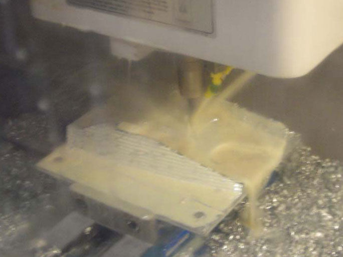
Machining of fishhead test part at Boeing Material & Process Technology Lab, Renton, WA, on an OKUMA MC-V4020.
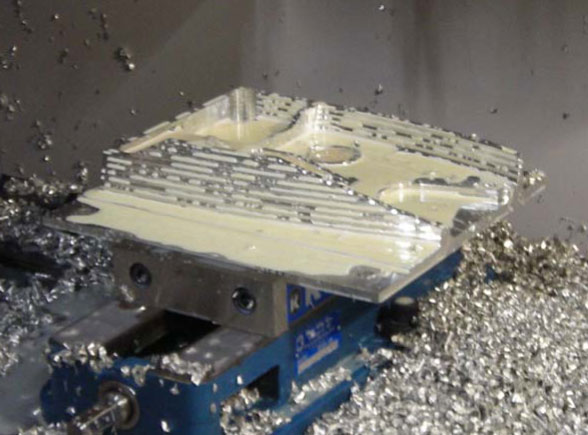
Completed fishhead test part machined at Boeing Material & Process Technology Lab.
Copyright © 2026 STEP Tools Inc. All Rights Reserved.
Legal notices and trademarks.
Legal notices and trademarks.