Tolerance-Driven Tool Compensation
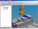
KTH Royal Institute of Technology, Eurostep, Sandvik Coromant, Scania, and STEP Tools demonstrated how STEP-NC machining information can integrate tolerances, wireless measuring equipment, and ISO 13399 tool descriptions to compensate for more accurate machining.
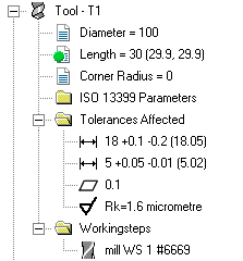
 A STEP-NC AP238 description can associate both tolerances, machining
operations, and the tools they use, with faces on the 3D geometry for
the machined part. During this demonstration, the STEP-NC Explorer
was extended to show these associations, as well as ISO 13399 in-use
parameters for the tools.
When machined, actual values for the tolerances were captured using hand-held wireless calipers. With these measured values (shown in parenthesis by the tolerance), the STEP-NC Explorer can recommend tool compensation values (shown in parenthesis by the tool parameter) by analyzing the tolerance stack-up using the linked geometry and machining information.
Whether the advised values or others are used, the compensation values are then sent to the CNC using its appropriate internal codes, such as the Siemens $TC_DPx registers. Along with the updated values, cutter contact toolpaths were also used for the finishing paths.
Over the course of the excercise, the STEP-NC Explorer was extended to read existing AP203e2 and AP214 geometry with tolerances, as well as annotate a model with new tolerances as described in the tutorial below.
Associated Files
- Scania Demonstration Overview [ppt, 4.8M]
- Making and Viewing Tolerances [ppt, 482k]
- Tolerance Stack-up and Compensation [ppt, 350k]
- kth_paths_tool_assemblies.238 [stepnc, 116k]
- scania_all_20080303.238 [stepnc, 114k]
- Part2_toleranced.stp [stp, 23k] (original part geometry with tolerances)

Video of demonstration at Scania, showing machining, measurement,
and tool compensation. (Updated 2008-10-22 with narration)
YouTube Video
Download: High quality [WMV, 36M]
Legal notices and trademarks.


