
| Integrated generic resource: Geometric and topological representation | ISO 10303-42:2021(E) © ISO |
The topology resource model has its basis in boundary representation solid modelling but can be used in any other application where an explicit method is required to represent connectivity.
The table below shows the symbols used in the description of the topology schema.
Table 2 — Topology symbol definitions
|
Symbol |
Definition |
|---|---|
| V | Vertex |
| V | Number of unique vertices |
| E | Undirected edge |
| E | Number of unique undirected edges |
| E l | Oriented edge |
| E l | Number of unique oriented edges |
| G e | Edge genus |
| P | Path |
| P | Number of unique paths |
| G p | Path genus |
| L | Loop |
| L | Number of unique loops |
| L l | Face bound |
| L l | Number of unique face bounds |
| L e | Edge loop |
| L p | Polyloop |
| L v | Vertex loop |
| G l | Loop genus |
| F | Face |
| F | Number of unique faces |
| H f | Face genus |
| S | Shell |
| S | Number of unique shells |
| S c | Closed shell |
| S o | Open shell |
| S v | Vertex shell |
| S w | Wire shell |
| H s | Shell genus |
| Ξ | Extent |
| { A } | Set of entities of type A |
| [ A ] | List of entities of type A |
Each implementation of an AP that uses this schema and that encodes entity names shall use the encoding specified in Annex A. Each reference to this schema in an open system shall use the identifier encoding specified in Annex B. This schema is illustrated in Annex D using the EXPRESS-G notation.
EXPRESS specification:
         *)

            	SCHEMA topology_schema;
            REFERENCE FROM
            basic_attribute_schema

               --
            ISO 10303-41
  (aggregate_id_attribute,


            get_aggregate_id_value,


            get_id_value,


            id_attribute,


            id_attribute_select);
            REFERENCE FROM
            geometry_schema;
               --
            ISO 10303-42
            REFERENCE FROM
            representation_schema

               --
            ISO 10303-43
  (representation,


            representation_item);
            REFERENCE FROM
            support_resource_schema

               --
            ISO 10303-41
  (bag_to_set,


            identifier);

(*
NOTE 1 The schemas referenced above are specified in the following parts:
basic_attribute_schema ISO 10303-41 geometry_schema ISO 10303-42 representation_schema ISO 10303-43 support_resource_schema ISO 10303-41
NOTE 2 See Annex D for a graphical representation of this schema.
The topological entities, vertex , edge etc., specified here have been defined independently of any use that may be made of them. Minimal constraints have been placed on each entity with the intention that any additional constraints will be specified by the using entity or by a defined context in which the entity is used. The intent is to avoid limiting the context or the use made of the entities. The only constraint is in the entity types provided for associating geometric information (see below, Geometric associations), for which specialised topological subtypes constitute the exclusive means of establishing direct associativity between geometric and topological elements at the integrated resource level.
The topological entities have been defined in a hierarchical manner with the vertex being the primitive entity. That is, all other topological entities are defined either directly or indirectly in terms of vertices.
Each entity has its own set of constraints. A higher-level entity may impose constraints on a lower-level entity. At the higher level, the constraints on the lower-level entity are the sum of the constraints imposed by each entity in the chain between the higher- and lower-level entities. The basic topological structures in order of increasing complexity are vertex , edge , path , loop , face , and shell.
In addition to the high-level structured topological entities open_shell and closed_shell , which are specialised subtypes of connected_face_set , the topology section includes the connected_edge_set and the general connected_face_set . These two entities are designed for the communication of collections of topological data where the constraints applied to shell are inappropriate.
The poly_loop is a loop with straight and coplanar edges and is defined as an ordered list of points. The poly_loop entity is used for the communication of faceted B-rep models. Many functions ensure consistency of the topology models by applying topological and geometric constraints to entities.
5.2.1 Geometric associations
Many of the topological entities have a specialised subtype which enables them to be associated with geometric data. This association will be essential when communicating complex geometric models in clause 6 composed of both geometric and topological entities, such as boundary representation solid models. The specialised subtypes of vertex , edge and face are vertex_point , edge_curve , and face_surface respectively. For the edge_curve and face_surface the relationship between the geometric sense and the topological sense of the associated entities is also recorded. The key concept relating geometry to topology is the domain. The domain of a point , curve , or surface is just that point, curve, or surface. The domain of a vertex , edge , or face is the corresponding point, curve, or surface. The domain of a loop or path is the union of the domains of all the vertices and edges in the loop or path . (Except in the case of a vertex loop, this is a curve.) The domain of a shell is the union of the domains of all the vertices, edges, and faces in the shell. (For a closed_shell or open_shell , this is a surface.) The domain of a solid model is the region of space it occupies. The domain of a set or list is the union of the domains of the elements of that set or list. Wherever in this standard a geometrical concept such as connectedness or finiteness is discussed in relation to an entity, it is understood that the concept applies to the domain of that entity.
A key concept in describing domains is the idea of a manifold. Intuitively, a domain is a d -manifold if it is locally indistinguishable from d -dimensional Euclidean space. This means that the dimensionality is the same at each mathematical point, and self- intersections are prohibited. As defined in this standard, curves and surfaces may contain self-intersections, and hence need not be manifolds. However, the part of a curve or surface that corresponds to the domain of a topological entity such as an edge or face shall be a manifold.
As used in this standard, the terms "manifold", "boundary" , and " manifold with boundary" are identical to the usual mathematical definitions. A manifold with boundary differs from a manifold in that the boundary is allowed, but not required, to be non-empty.
A 1-manifold is a non-self-intersecting curve which does not include either of its end points. Examples of 1-manifolds are the real line and the unit circle. A "Y"-shaped figure is not a 1-manifold, and neither is the closed unit interval. A 2-manifold is a non-self-intersecting surface which does not include boundary curves. Examples of 2-manifolds include the unit sphere and the open disk {(x,y,0) : x 2 + y 2 < 1\} . The closed disk {(x,y,0) : x 2 + y 2 ≤ 1} is not a manifold. The domains of edges and paths, if present, are 1-manifolds. The domains of faces and closed shells, if present, are 2-manifolds.
Any curve which does not self-intersect is a 1-manifold with boundary. The closed disk {(x,y,0) : x 2 + y 2 ≤ 1} is a 2-manifold with boundary. The domain of an open shell, if present, is a 2-manifold with boundary. The domain of a manifold solid boundary representation or a faceted manifold boundary representation is a 3-manifold with boundary.
The boundary of a d -manifold with boundary is a (d-1) -manifold. For example, the boundary of a curve is the set of 0, 1, or 2 end points contained in that curve. The boundary of the closed disk {(x,y,0) : x 2 + y 2 ≤ 1} is the unit circle. The boundary of the domain of an open shell is the domain of the set of loops that bound holes in the shell. The boundary of a manifold solid boundary representation or a faceted manifold boundary representation is the domain of the set of bounding shells.
Curves and surfaces which are manifolds with boundary are classified as either open or closed. The terms "open" and "closed", when applied to curves or surfaces in this standard, should not be confused with the notions of "open set" or "closed set" from point set topology. The term "closed surface" is identical to the usual definition of a closed, connected, orientable 2-manifold. Examples of a closed surface are a sphere and a torus. The domain of a closed shell, if present, is a closed surface. Examples of open surfaces are an infinite plane, or a surface with one or more holes. The domain of an open shell, if present, is an open surface.
All closed surfaces that are physically manufacturable are orientable. Face domains, because they are always embeddable in the plane, are orientable. Open surfaces need not be orientable. For example, the Möbius strip is an open surface. Also, some manifolds are neither open nor closed as defined in this standard. The Klein bottle is an example. It is finite and its boundary is empty, but the surface is not orientable, and hence does not divide space into two regions. However, the domain of an open shell as defined in this standard must be orientable.
The term "genus" refers to an integer-valued function used to classify topological properties of an entity. This standard defines two different types of genus.
For an entity which can be described as a graph of edges and vertices, for example a loop, path, or wire shell, genus is equivalent to the standard technical term "cycle rank" in graph theory. It is not equivalent to the standard usage of the term "genus" in graph theory. Intuitively, it measures the number of independent cycles in a graph. For example, a graph with exactly one vertex, joined to itself by n self-loops, has genus n .
The genus of a closed surface X is the number of handles that must be added to a sphere to produce a surface homeomorphic to X. For example, the genus of a sphere is 0, and the genus of a torus is 1. This is identical to the standard technical term "genus of a surface" from algebraic topology. Adding a handle to a closed surface is the operation that corresponds to drilling a tunnel through the three-dimensional volume bounded by that surface. This can be viewed as cutting out two disks and connecting their boundaries with a cylindrical tube. Handles should not be confused with holes. As used in this standard, the term "hole" corresponds to the intuitive notion of punching a hole in a two-dimensional surface.
The surface genus definition is extended to orientable open surfaces as follows. Fill in every hole in the domain with a disk. The resulting surface is a closed surface, for which genus is already defined. Use this number for the genus of the open surface.
5.2.2 Associations with parameter space geometry
A fundamental assumption in this clause is that the topology being defined is that of model space. The geometry of curves and points can also be defined in parameter space but, in general, the topological structure of, for example a face , will not be the same in the parametric space of the underlying surface as it is in model space.
Parametric space modelling systems differ from real space systems in the methodology used to associate geometry to topology. Parametric space modelling systems typically associate a different parametric space curve with each edge use (i.e., oriented_edge ). Every one of the parametric space curves associated with a given edge (by way of an edge use) describe the same point set in real space. The parametric space curves are defined in different parametric spaces. The parametric spaces are the surfaces which underlay the faces bordering on the edge. In a manifold solid the geometry of every edge is defined twice, once for each of the two face s which border on that edge .
Associating a parametric space curve with each edge use extends naturally to the use of degenerate edges (i.e., edges with zero length in real space). For example, a parametric space modelling system could represent a face that is triangular in real space as a square in parametric space. A straight forward way to do this is to represent one of the triangular face's vertices as a degenerate edge (but having two vertices); then there is a one-to-one mapping between edges in real space and model space. The degenerate edge has zero length in real space, but greater than zero length in parametric space. Degenerate edges also may be used for creating bounds around singularities such as the apex of a cone.
Real space modelling systems do not associate parametric space curves with each edge use nor do they allow degenerate edges. Since the parametric space modelling systems treatment of topology is an implementation convenience, this standard requires the use of real space topology. The parametric space modelling system's unique information requirements are satisfied using techniques at the geometric level.
5.2.2.1 Edge_curve associations with parametric space curves
Techniques that can be used to associate parametric space curves with an edge_curve are:
These techniques are formally defined in EXPRESS as the function edge_curve_pcurves which can be used to determine all the parametric space curves associated with a particular edge .
NOTE 1 For applications where the real space modelling systems are not required to understand parametric space curves, the parametric space modelling systems should be required to use only the third technique described above. Then, even if the pcurve s are ignored, the real space modelling system will have the correct geometry associated with all edge_curve s.
NOTE 2 Given the pcurve s of an edge_curve , determining which oriented_edge a pcurve shall be associated with is a matter of matching (:=:) the basis_surface of the pcurve with the face_geometry of the face bound by that oriented_edge . If two or more pcurve s are associated with the same edge_curve and are defined in the parametric space of the same surface, determining which oriented_\-edge the pcurve is associated with requires checking connectivity of the pcurve s in parametric space.
5.2.3 Graphs, cycles, and traversals
A connected component of a graph is a connected subset of the graph which is not contained in any larger connected subset. We denote by M the multiplicity of a graph, that is, the number of connected components. Thus, a graph is connected if and only if M = 1 .
Each component of a graph can be completely traversed, starting, and ending at the same vertex, such that every edge is traversed exactly twice, once in each direction, and every vertex is "passed through" the same number of times as there are edges using the vertex. If an (edge + edge traversal direction) is considered as a unit, each unique (edge + direction) combination shall occur once and only once in the traversal of a graph. During the traversal of a graph it will be found that there are one or more sets of alternating vertices and (edge + direction) units that form closed cycles.
The symbol G will denote the graph genus , which is, intuitively, the number of independent cycles in the graph. (Technically, G is the rank of the fundamental group of the graph.)
Every graph satisfies the following Euler equation
(V - E) - (M - G) = 0
where V and E are the numbers of unique vertices and edges in the graph.
NOTE 3 The following graph traversal algorithm, [16], may be used to traverse a graph and compute M and G .
EXPRESS specification:
            *)

            CONSTANT

(*
A dummy_tri is a constant that is a partial entity definition to be used when types of topological_representation_item are constructed. It provides the correct supertypes and the name attribute as an empty string.
EXPRESS specification:
            *)

              dummy_tri
            : topological_representation_item := representation_item('')||
            topological_representation_item();

(*
            *)

            END_CONSTANT;

(*
EXPRESS specification:
            *)

            TYPE
            list_of_reversible_topology_item
            =
            LIST[0:?] OF reversible_topology_item;

            END_TYPE;

            (*
EXPRESS specification:
            *)

            TYPE
            reversible_topology
            =


            SELECT

               (reversible_topology_item,
    list_of_reversible_topology_item,
    set_of_reversible_topology_item);

            END_TYPE;

            (*
EXPRESS specification:
            *)

            TYPE
            reversible_topology_item
            =


            SELECT

               (edge,
    path,
    face,
    face_bound,
    closed_shell,
    open_shell);

            END_TYPE;

            (*
EXPRESS specification:
            *)

            TYPE
            set_of_reversible_topology_item
            =
            SET[0:?] OF reversible_topology_item;

            END_TYPE;

            (*
The shell type collects together, for reference when constructing more complex models, the subtypes which have the characteristics of a shell.
A shell is a connected object of fixed dimensionality d = 0, 1, or 2, typically used to bound a region. The domain of a shell, if present, includes its bounds and 0 ≤ Ξ < ∞
A shell of dimensionality 0 is represented by a graph consisting of a single vertex. The vertex shall not have any associated edges.
A shell of dimensionality 1 is represented by a connected graph of dimensionality 1.
A shell of dimensionality 2 is a topological entity constructed by joining faces along edges. Its domain, if present, is a connected, orientable 2-manifold with boundary, that is, a connected, oriented, finite, non-self-intersecting surface, which may be closed or open.
EXPRESS specification:
            *)

            TYPE
            shell
            =


            SELECT

               (vertex_shell,
    wire_shell,
    open_shell,
    closed_shell);

            END_TYPE;

            (*
EXPRESS specification:
            *)

            TYPE
            tri_id_attribute_select
            =


            SELECT
            BASED_ON
            id_attribute_select
            WITH


               (topological_representation_item);

            END_TYPE;

            (*
A topological_representation_item is a type of representation_item that represents the topology, or connectivity, of entities which make up the representation of an object. The topological_representation_item is the supertype for all the representation items in the topology schema.
NOTE 1 As subtypes of representation_item there is an implicit and/or relationship between geometric_representation_item and topological_representation_item. The only complex instances intended to be created are edge_curve, face_surface, and vertex_point.
NOTE 2 The definition of topological_representation_item defines an and/or relationship between loop and path. The only valid complex instance is the edge_loop entity.
EXPRESS specification:
            *)

            ENTITY topological_representation_item

              SUPERTYPE OF (ONEOF (vertex,
                       edge,
                       face_bound,
                       face,
                       vertex_shell,
                       wire_shell,
                       connected_edge_set,
                       connected_face_set,
                       connected_volume_set,
                       volume_with_faces, (
                       loop
               ANDOR path)))

              SUBTYPE OF (representation_item);
DERIVE

              permanent_id : identifier := get_id_value(SELF);

              permanent_aggregate_id : identifier := get_aggregate_id_value(SELF);
WHERE

              WR1: SIZEOF(USEDIN(SELF,'BASIC_ATTRIBUTE_SCHEMA.ID_ATTRIBUTE.IDENTIFIED_ITEM')) <= 1;

              WR2: SIZEOF(USEDIN(SELF,'BASIC_ATTRIBUTE_SCHEMA.AGGREGATE_ID_ATTRIBUTE.IDENTIFIED_ITEM')) <= 1;

            END_ENTITY;
(*
Attribute definitions:
permanent_id: an identifier that distinguishes the topological_representation_item.
NOTE 3 This attribute is an enhancement to the definition of topological_representation_item using a method that is upwardly compatible with ISO 10303-42.
NOTE 4 The meaning of this attribute can be defined in the annotated EXPRESS schemas that use or specialize this entity, or in an agreement of common understanding between the partners sharing this information.
NOTE 5 The context in which permanent_id is used as a discriminating characteristic can be identified in an annotated Express schema that uses or specializes this entity, or by default, in an agreement of common understanding between partners sharing this information.
permanent_aggregate_id: an identifier that distinguishes the topological_representation_item. A permanent_aggregate_id supports the assignment of more than one instance of topological_representation_item to the same identifier.
NOTE 6 This attribute is an enhancement to the definition of topological_representation_item using a method that is upwardly compatible with ISO 10303-42.
NOTE 7 The meaning of this attribute can be defined in the annotated EXPRESS schemas that use or specialize this entity, or in an agreement of common understanding between the partners sharing this information.
NOTE 8 The context in which permanent_aggregate_id is used as a discriminating characteristic can be identified in an annotated Express schema that uses or specializes this entity, or by default, in an agreement of common understanding between partners sharing this information.
Formal propositions:
WR1: Each topological_representation_item shall be the identified_item in at most one id_attribute.
NOTE 9 The id_attribute data type is defined in basic_attribute_schema of ISO 10303-42.
NOTE 10 A template for constraining the population of the entity data types defined in the basic_attribute_schema is described in annex E of ISO 10303-41.
WR2: Each topological_representation_item shall be the identified_item in at most one aggregate_id_attribute.
NOTE 11 The aggregate_id_attribute data type is defined in basic_attribute_schema of ISO 10303-42.
Informal propositions:
IP1: For each topological_representation_item, consider the set of edges, edge_curve, and face_surfaces that are referenced, either directly or recursively, from that topological_representation_item. (Do not include in this set oriented edges or faces, but do include the non-oriented edges and faces on which they are based.) Then no two distinct elements in this set shall have domains that intersect.
A vertex is a type of topological_representation_item, and is the topological construct corresponding to a point. It has dimensionality 0 and extent 0. The domain of a vertex, if present, is a point in m dimensional real space Rm; this is represented by the vertex_point subtype.
EXPRESS specification:
            *)

            ENTITY vertex

              SUBTYPE OF (topological_representation_item);

            END_ENTITY;
(*
Informal propositions:
IP1: The vertex has dimensionality 0. This is a fundamental property of the vertex.
IP2: The extent of a vertex is defined to be zero.
EXPRESS specification:
            *)

            ENTITY vertex_point

              SUBTYPE OF (vertex, geometric_representation_item);


              vertex_geometry : point;

            END_ENTITY;
(*
Attribute definitions:
vertex_geometry: the geometric point which defines the position in geometric space of the vertex;
Informal propositions:
IP1: The domain of the vertex is formally defined to be the domain of its vertex_geometry.
An edge is a type of topological_representation_item, corresponding to the connection between two vertices. More abstractly, it may stand for a logical relationship between the two vertices. The domain of an edge, if present, is a finite, non-self-intersecting open curve in Rm, that is, a connected 1-dimensional manifold. The bounds of an edge are two vertices, which need not be distinct. The edge is oriented by choosing its traversal direction to run from the first to the second vertex. If the two vertices are the same, the edge is a self-loop. The domain of the edge does not include its bounds, and 0 < Ξ < ∞.
Associated with an edge may be a geometric curve to locate the edge in a coordinate space; this is represented by the edge_curve subtype. The curve shall be finite and non-self-intersecting within the domain of the edge. An edge is a graph, so its multiplicity M and graph genus Ge may be determined by the graph traversal algorithm. Since M = E = 1, the Euler equation reduces in this case to
V - (2 - Ge) = 0 (2)
where V = 1 or 2, and Ge = 1 or 0.
Specifically, the topological edge defining data shall satisfy:
EXPRESS specification:
            *)

            ENTITY edge

              SUPERTYPE OF (ONEOF (edge_curve,
                       oriented_edge,
                       subedge))

              SUBTYPE OF (topological_representation_item);


              edge_start : vertex;


              edge_end : vertex;

            END_ENTITY;
(*
Attribute definitions:
edge_start: start point (vertex) of the edge.
edge_end: end point (vertex) of the edge. The same vertex can be used for both edge_start and edge_end.
Informal propositions:
IP1: The edge has dimensionality 1.
IP2: The extent of an edge shall be finite and nonzero.
An edge_curve is a type of edge, which has its geometry fully defined. The geometry is defined by associating the edge with a curve which may be unbounded. As the topological and geometric directions may be opposed, an indicator (same_sense) is used to identify whether the edge and curve directions agree or are opposed. The Boolean value indicates whether the curve direction agrees with (TRUE) or is in the opposite direction (FALSE) to the edge direction. Any geometry associated with the vertices of the edge shall be consistent with the edge geometry. Multiple edges can reference the same curve.
EXPRESS specification:
            *)

            ENTITY edge_curve

              SUBTYPE OF (edge, geometric_representation_item);


              edge_geometry : curve;


              same_sense : BOOLEAN;

            END_ENTITY;
(*
Attribute definitions:
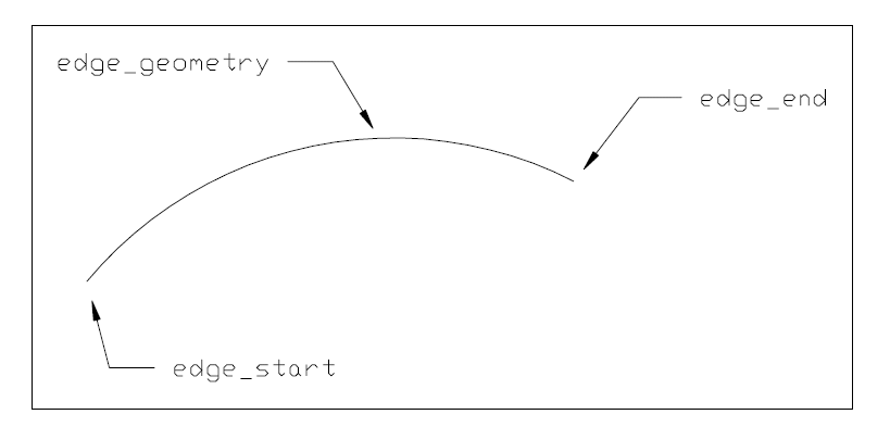
edge_geometry: the curve which defines the shape and spatial location of the edge. This curve may be unbounded and is implicitly trimmed by the vertices of the edge; this defines the edge domain.
same_sense: a logical flag which indicates whether (TRUE), or not (FALSE) the senses of the edge and the curve defining the edge geometry are the same. The sense of an edge is from the edge start vertex to the edge end vertex; the sense of a curve is in the direction of increasing parameter.
NOTE See Figure (25) for illustration of attributes.
Informal propositions:
IP1: The domain of the edge_curve is formally defined to be the domain of its edge_geometry as trimmed by the vertices. This domain does not include the vertices.
IP2: The extent of an edge_curve shall be finite and nonzero.
IP3: An edge_curve is a manifold.
IP4: An edge_curve is arcwise connected.
IP5: The edge start is not part of the edge domain.
IP6: The edge end is not part of the edge domain.
IP7: Vertex geometry shall be consistent with edge geometry.
An oriented_edge is a type of edge, constructed from another edge and contains a BOOLEAN orientation flag to indicate whether or not the orientation of the constructed edge agrees with the orientation of the original edge. Except for possible re-orientation, the oriented_edge is equivalent to the original edge.
NOTE A common practice in solid modelling systems is to have an entity that represents the " use" or " traversal " of an edge. This "use" entity explicitly represents the requirement in a manifold solid that each edge must be traversed exactly twice, once in each direction. The "use" functionality is provided by the edge subtype oriented_edge.
EXPRESS specification:
            *)

            ENTITY oriented_edge

              SUBTYPE OF (edge);


              edge_element : edge;


              orientation : BOOLEAN;
DERIVE

              SELF\edge.edge_start : vertex := boolean_choose (SELF.orientation,
            SELF.edge_element.edge_start,
            SELF.edge_element.edge_end);

              SELF\edge.edge_end : vertex := boolean_choose (SELF.orientation,
            SELF.edge_element.edge_end,
            SELF.edge_element.edge_start);
WHERE

              WR1: NOT ('TOPOLOGY_SCHEMA.ORIENTED_EDGE' IN TYPEOF (SELF.edge_element));

            END_ENTITY;
(*
Attribute definitions:
edge_element: an edge entity used to construct this oriented_edge;
orientation: a BOOLEAN, if TRUE, the topological orientation as used coincides with the orientation, from start vertex to end vertex, of the edge_element.
edge_start: the start vertex of the oriented edge, this is derived from the vertices of the edge_element after taking account of the orientation.
edge_end: the end vertex of the oriented edge, this is derived from the vertices of the edge_element after taking account of the orientation.
Formal propositions:
WR1: The edge_element shall not be an oriented_edge.
A seam_edge is a type of oriented_edge, which, additionally, identifies a corresponding pcurve. A seam_edge is always related to an edge_curve having a seam_curve as edge_geometry. The seam_edge identifies which, of the two pcurves defining the seam_curve, is appropriate for this oriented_edge.
NOTE The inherited orientation attribute refers to the relationship to the edge_element and not to the sense of the pcurve.
EXPRESS specification:
            *)

            ENTITY seam_edge

              SUBTYPE OF (oriented_edge);


              pcurve_reference : pcurve;
WHERE

              WR1: ( 'TOPOLOGY_SCHEMA.EDGE_CURVE' IN TYPEOF (edge_element) )  AND
            ('TOPOLOGY_SCHEMA.SEAM_CURVE' IN TYPEOF
            (edge_element\edge_curve.edge_geometry));

              WR2: pcurve_reference IN edge_element\edge_curve.edge_geometry\
            surface_curve.associated_geometry;

            END_ENTITY;
(*
Attribute definitions:
pcurve_reference: the pcurve associated with the current orientation of the edge_element;
Formal propositions:
WR1: the edge_element attribute of this type of oriented edge shall be a seam_curve.
WR2: The pcurve_reference shall be one of the pcurves in the associated_geometry list of the edge_element.
A subedge is a type of edge, whose domain is a connected portion of the domain of an existing edge. The topological constraints on a subedge are the same as those on an edge.
EXPRESS specification:
            *)

            ENTITY subedge

              SUBTYPE OF (edge);


              parent_edge : edge;
WHERE

              WR1: SELF :<>: parent_edge;

            END_ENTITY;
(*
Attribute definitions:
parent_edge: the edge, or subedge, which contains the subedge.
Formal propositions:
WR1: An instance of subedge shall not also be the instance of edge in the role of parent_edge.
Informal propositions:
IP1: The domain of the subedge is formally defined to be the domain of the parent_edge, as trimmed by the subedge.edge_start and subedge.edge_end.
IP2: The edge_start and edge_end shall be within the union of the domains of the vertices of the parent_edge and the domain of the parent_edge.
A path is a type of topological_representation_item, consisting of an ordered collection of oriented_edges, such that the edge_start vertex of each edge coincides with the edge_end of its predecessor. The path is ordered from the edge_start of its first oriented_edge to the edge_end of its last oriented_edge.
The BOOLEAN value orientation in the oriented_edge indicates whether the edge direction agrees with the direction of the path (TRUE) or is in the opposite direction (FALSE).
An individual edge can only be referenced once by an individual path.
An edge can be referenced by multiple paths. An edge can exist independently of a path.
EXPRESS specification:
            *)

            ENTITY path

              SUPERTYPE OF (ONEOF (open_path,
                       edge_loop,
                       oriented_path))

              SUBTYPE OF (topological_representation_item);


              edge_list : LIST[1:?] OF
            UNIQUE
            oriented_edge;
WHERE

              WR1: path_head_to_tail(SELF);

            END_ENTITY;
(*
Attribute definitions:
edge_list: the list of oriented_edge entities which are concatenated together to form this path.;
Formal propositions:
WR1: The end vertex of each oriented_edge shall be the same as the start vertex of its successor.
Informal propositions:
IP1: A path has dimensionality 1.
IP2: A path is arcwise connected.
IP3: The edges of the path do not intersect except at common vertices.
IP4: A path has a finite, non-zero extent.
IP5: No path shall include two oriented edges with the same edge element and the same orientation.
EXPRESS specification:
            *)

            ENTITY subpath

              SUBTYPE OF (path);


              parent_path : path;
WHERE

              WR1: SELF :<>: parent_path;

              WR2: NOT (('TOPOLOGY_SCHEMA.EDGE_LOOP' IN TYPEOF(SELF)) AND ('TOPOLOGY_SCHEMA.OPEN_PATH' IN TYPEOF(parent_path)));

            END_ENTITY;
(*
Attribute definitions:
parent_path: the path, which contains the subpath.
Formal propositions:
WR1: An instance of subpath shall not also be the instance of path in the role of parent_path.
WR2: An instance of subpath that is an edge_loop shall not reference an instance of open_path in the role of parent_path.
Informal propositions:
IP1: The domain of the subpath shall be within the domain of the parent_path.
IP2: If the subpath is an edge_loop, the domain of the subpath shall be the same as the parent_path.
NOTE 1 The domain of the subpath that is an edge_loop is not a proper subset of the domain of the parent_path when that parent_path is also an edge_loop.
IP3: If the subpath is an edge_loop and the parent_path is an oriented_path, the oriented_path shall be closed to form a loop.
NOTE 2 The orientation of the subpath and parent_path loops can be different if the subpath is an edge_loop and the parent_path is an oriented_path.
An oriented_path is a type of path, constructed from another path and contains a BOOLEAN orientation flag to indicate whether or not the orientation of the constructed path agrees with the orientation of the original path. Except for perhaps orientation, the oriented_path is equivalent to the other path.
EXPRESS specification:
            *)

            ENTITY oriented_path

              SUBTYPE OF (path);


              path_element : path;


              orientation : BOOLEAN;
DERIVE

              SELF\path.edge_list : LIST[1:?] OF
            UNIQUE
            oriented_edge := conditional_reverse(SELF.orientation,
            SELF.path_element.edge_list);
WHERE

              WR1: NOT ('TOPOLOGY_SCHEMA.ORIENTED_PATH' IN TYPEOF (SELF.path_element));

            END_ENTITY;
(*
Attribute definitions:
path_element: the path entity used to construct this oriented_path;
orientation: a BOOLEAN, if TRUE, the topological orientation as used coincides with the orientation of the path_element;
edge_list: the list of oriented_edges which form the oriented_path; this list is derived from the path_element after taking account of the orientation attribute;
Formal propositions:
WR1: The path_element shall not be an oriented_path.
An open_path is a type of path, such that a traversal of the path visits each of its vertices exactly once. In particular, the start vertex and end vertex are different. An open_path is a graph for which M = 1 and Gp = 0, so the Euler equation (1) reduces in this case to
(V - E) - 1 = 0 (3)
where V and E are the number of unique vertices and edges in the path. Specifically, the topological attributes of a path shall meet the following constraints:
(P)[E] = (P){E}
|((P)[E]){V}| - |(P){E}| - 1 = 0
EXPRESS specification:
            *)

            ENTITY open_path

              SUBTYPE OF (path);
DERIVE

              ne : INTEGER := SIZEOF(SELF\path.edge_list);
WHERE

              WR1: (SELF\path.edge_list[1].edge_element.edge_start) :<>:
            (SELF\path.edge_list[ne].edge_element.edge_end);

            END_ENTITY;
(*
Attribute definitions:
ne: the number of elements in the edge list of the path supertype;
Formal propositions:
WR1: The start vertex of the first edge shall not coincide with the end vertex of the last edge.
Informal propositions:
IP1: An open_path visits its vertexs exactly once. This implies that if a list of vertices is constructed from the edge data the first and last vertex will occur once in this list and all other vertices will occur twice.
A loop is a type of topological_representation_item, constructed from a single vertex, or by stringing together connected (oriented) edges, or linear segments beginning and ending at the same vertex. A loop has dimensionality 0 or 1. The domain of a 0-dimensional loop is a single point. The domain of a 1-dimensional loop is a connected, oriented curve, but need not be a manifold. As the loop is a cycle, the location of its beginning/ending point is arbitrary. The domain of the loop includes its bounds, and 0 ≤ Ξ < ∞
A loop is represented by a single vertex, or by an ordered collection of oriented_edges, or by an ordered collection of points.
A loop is a graph, so M and the graph genus Gl may be determined by the graph traversal algorithm. Since M = 1, the Euler equation reduces in this case to
(V - El) - (1 - Gl) = 0 (4)
where V and E are the number of unique vertices and oriented edges in the loop and Gl is the genus of the loop.
EXPRESS specification:
            *)

            ENTITY loop

              SUPERTYPE OF (ONEOF (vertex_loop,
                       edge_loop,
                       poly_loop))

              SUBTYPE OF (topological_representation_item);

            END_ENTITY;
(*
Informal propositions:
IP1: A loop has a finite, or, in the case of the vertex_loop, zero extent.
IP2: A loop describes a closed (topological) curve with coincident start and end vertices.
A vertex_loop is a type of loop, of zero genus consisting of a single vertex. A vertex can exist independently of a vertex_loop. The topological data shall satisfy the following constraint:
Euler equation (4) shall be satisfied:
|(L){V}| - 1 = 0
EXPRESS specification:
            *)

            ENTITY vertex_loop

              SUBTYPE OF (loop);


              loop_vertex : vertex;

            END_ENTITY;
(*
Attribute definitions:
loop_vertex: the vertex which defines the entire loop;
Informal propositions:
IP1: A vertex_loop has zero extent and dimensionality.
IP2: The vertex_loop has genus 0.
An edge_loop is a type of loop, with nonzero extent. It is a path in which the start and end vertices are the same. Its domain, if present, is a closed curve. An edge_loop may overlap itself.
EXPRESS specification:
            *)

            ENTITY edge_loop

              SUBTYPE OF (loop, path);
DERIVE

              ne : INTEGER := SIZEOF(SELF\path.edge_list);
WHERE

              WR1: (SELF\path.edge_list[1].edge_start) :=:
            (SELF\path.edge_list[ne].edge_end);

            END_ENTITY;
(*
Attribute definitions:
ne: the number of elements in the edge list of the loop supertype.
Formal propositions:
WR1: The start vertex of the first edge shall be the same as the end vertex of the last edge; this ensures that the path is closed to form a loop.
Informal propositions:
IP1: The Euler formula shall be satisfied: (number of vertices) + genus - (number of edges) = 1.
IP2: No edge may be referenced more than once by the same edge_loop with the same orientation.
A poly_loop is a type of loop, with straight edges bounding a planar region in space. A poly_loop is a loop of genus 1 where the loop is represented by an ordered coplanar collection of points forming the vertices of the loop. The loop is composed of straight-line segments joining a point in the collection to the succeeding point in the collection. The closing segment is from the last to the first point in the collection. The direction of the loop is in the direction of the line segments. Unlike the loop entity, the edges of the poly_loop are implicitly defined by the polygon points.
NOTE 1 This entity exists primarily to facilitate the efficient communication of faceted boundary representation models.
NOTE 2 The poly_loop has vertices and oriented_edges which are implicitly created. If, for example, A and B are consecutive points in the polygon list, there is an implicit oriented_edge from vertex point A to vertex point B with orientation value TRUE. It is assumed that when the higher-level entities such as shell and B-rep require checks on edge usage that this check will recognise, for example, a straight oriented edge from point B to point A with orientation TRUE as equal to an oriented edge from A to B with orientation FALSE.
A poly_loop shall conform to the following topological constraints:
Euler equation (4) shall be satisfied:
|(L){V}| - |(L){El}| = 0
EXPRESS specification:
            *)

            ENTITY poly_loop

              SUBTYPE OF (loop, geometric_representation_item);


              polygon : LIST[3:?] OF
            UNIQUE
            cartesian_point;

            END_ENTITY;
(*
Attribute definitions:
polygon: a list of points defining the loop; there are no repeated points in the list;
Informal propositions:
IP1: All the points in the polygon defining the poly_loop shall be coplanar.
IP2: The implicit edges of the poly_loop shall not intersect each other. The implicit edges are the straight lines joining consecutive points in the polygon.
A face_bound is a type of topological_representation_item, and is a loop which is intended to be used for bounding a face.
EXPRESS specification:
            *)

            ENTITY face_bound

              SUBTYPE OF (topological_representation_item);


              bound : loop;


              orientation : BOOLEAN;

            END_ENTITY;
(*
Attribute definitions:
bound: the loop which will be used as a face boundary;
orientation: indicates whether (TRUE), or not (FALSE) the loop has the same sense when used to bound the face as when first defined; if orientation is FALSE, the senses of all its component oriented edges are implicitly reversed when used in the face;
A face_outer_bound is a type of face_bound, which carries the additional semantics of defining an outer boundary on the face. A face_outer_bound shall separate the interior of the face from the exterior and shall enclose the interior domain of the face.
No more than one boundary of a face shall be of this type.
EXAMPLE 1 Any edge_loop on a plane surface may be used to define a face_outer_bound provided it is not enclosed in any other loop in the face.
EXAMPLE 2 A circular loop on a cylindrical surface cannot define a face_outer_bound since it does not enclose a closed domain in the surface.
EXPRESS specification:
            *)

            ENTITY face_outer_bound

              SUBTYPE OF (face_bound);

            END_ENTITY;
(*
A face is a type of topological_representation_item, of dimensionality 2 corresponding to the intuitive notion of a piece of surface bounded by loops. Its domain, if present, is an oriented, connected, finite 2-manifold in Rm. A face domain shall not have handles, but it may have holes, each hole bounded by a loop. The domain of the underlying geometry of the face, if present, does not contain its bounds, and 0 < Ξ < ∞. A face is represented by its bounding loops, which are defined as face_bounds. A face shall have at least one bound, and the bounds shall be distinct and shall not intersect. One loop is optionally distinguished, using the face_outer_bound subtype, as the "outer" loop of the face. If so, it establishes a preferred way of embedding the face domain in the plane, in which the other bounding loops of the face are "inside" the outer loop. Because the face domain is arcwise connected, no inner loop shall contain any other loop. This is true regardless of which embedding in the plane is chosen.
A geometric surface may be associated with the face. This may be done explicitly through the face_surface subtype, or implicitly if the faces are defined by poly_loops. In the latter case, the surface is the plane containing the points of the poly_loops. In either case, a topological normal n is associated with the face, such that the cross product n × t points toward the interior of the face, where t is the tangent to a bounding loop. That is, each loop runs counter-clockwise around the face when viewed from above, if we consider the normal n to point up. Each loop is associated through a face_bound entity with a BOOLEAN flag to signify whether the loop direction is oriented correctly with respect to the face normal (TRUE) or should be reversed (FALSE). For a face of the subtype face_surface, the topological normal n is defined from the normal of the underlying surface, together with the BOOLEAN attribute same_sense, and this in turn, determines on which side of the loop the face interior lies, using the cross-product rule described above.
When a vertex_loop is used as a face_bound the sense of the topological normal is derived from any other bounding loops, or, in the case of a face_surface, from the face_geometry and the same_sense flag. If the face has only one bound and this is of type vertex_loop, then the interior of the face is the domain of the face_geometry. In such a case the underlying surface shall be closed (such as a spherical surface.)
The situation is different for a face on an implicit planar surface, such as one defined by poly_loops, which has no unique surface normal. Since the face and its bounding loops lie in a plane, the outer loop can always be found without ambiguity. Since the face is required to be finite, the face interior must lie inside the outer loop, and outside each of the remaining loops. These conditions, together with the specified loop orientations, define the topological normal n using the cross-product rule described above. All poly_loop orientations for a given face shall produce the same value for n.
The edges and vertices referenced by the loops of a face form a graph, of which the individual loops are the connected components. The Euler equation for this graph becomes:
(V - E) - (L - ΣLi=1 (Gil)) = 0 (5)
where Gil is the graph genus of the i th loop.
More specifically, the following topological constraints shall be met:
((F)[L])\{El} = ((F)[L])[El]
Equation (5) shall be satisfied
|(((F)[Le]){E}){V}| + |((F)[Lv]){V}| - |((F)[L]){E}| - |(F)[L]| + ΣGl = 0
EXPRESS specification:
            *)

            ENTITY face

              SUPERTYPE OF (ONEOF (face_surface,
                       subface,
                       oriented_face))

              SUBTYPE OF (topological_representation_item);


              bounds : SET[1:?] OF face_bound;
WHERE

              WR1: NOT (mixed_loop_type_set(list_to_set(list_face_loops(SELF))));

              WR2: SIZEOF(QUERY(temp <* bounds | 'TOPOLOGY_SCHEMA.FACE_OUTER_BOUND' IN
            TYPEOF(temp))) <= 1;

            END_ENTITY;
(*
Attribute definitions:
bounds: boundaries of the face; no more than one of these shall be a face_outer_bound;
NOTE For some types of closed or partially closed surfaces, it may not be possible to identify a unique outer bound.
Formal propositions:
WR1: If any loop of the face is a poly loop, all loops of the face shall be poly loops.
WR2: At most, one of the bounds shall be of type face_outer_bound.
Informal propositions:
IP1: No edge shall be referenced by the face more than twice, or, more than once in the same direction.
IP2: Distinct face_bounds of the face shall have no common vertices.
IP3: If geometry is present, distinct loops of the same face shall not intersect.
IP4: The face shall satisfy the Euler equation (see equation (5)):
(number of vertices) - (number of edges) - (number of loops) + (sum of genus for loops) = 0.
IP5: Each loop referred to in bounds shall be unique.
A face_surface is a type of face, in which the geometry is defined by an associated surface. The portion of the surface used by the face shall be embeddable in the plane as an open disk, possibly with holes. However, the union of the face with the edges and vertices of its bounding loops need not be embeddable in the plane. It may, for example, cover an entire sphere or torus. As both a face and a geometric surface have defined normal directions, a BOOLEAN flag (the orientation attribute) is used to indicate whether the surface normal agrees with (TRUE) or is opposed to (FALSE) the face normal direction. The geometry associated with any component of the loops of the face shall be consistent with the surface geometry, in the sense that the domains of all the vertex points and edge curves are contained in the face geometry surface. A surface may be referenced by more than one face_surface.
EXPRESS specification:
            *)

            ENTITY face_surface

              SUBTYPE OF (face, geometric_representation_item);


              face_geometry : surface;


              same_sense : BOOLEAN;
WHERE

              WR1: NOT ('GEOMETRY_SCHEMA.ORIENTED_SURFACE' IN TYPEOF(face_geometry));

            END_ENTITY;
(*
Attribute definitions:
face_geometry: the surface which defines the internal shape of the face; this surface may be unbounded; the domain of the face is defined by this surface and the bounding loops in the inherited attribute bounds;
same_sense: flag indicates whether the sense of the surface normal agrees with (TRUE), or opposes (FALSE), the sense of the topological normal to the face;
Formal propositions:
WR1: An oriented_surface shall not be used to define the face_geometry.
Informal propositions:
IP1: The domain of the face_surface is formally defined to be the domain of its face_geometry as trimmed by the loops, this domain does not include the bounding loops.
IP2: A face_surface has nonzero finite extent.
IP3: A face_surface is a manifold.
IP4: A face_surface is arcwise connected.
IP5: A face_surface has surface genus 0.
IP6: The loops are not part of the face domain.
IP7: Loop geometry shall be consistent with face geometry. This implies that any edge_curves or vertex_points used in defining the loops bounding the face_surface shall lie on the face_geometry.
IP8: The loops of the face shall not intersect.
An oriented_face is a type of face, which contains an additional orientation BOOLEAN flag to indicate whether, or not, the sense of the oriented face agrees with its sense as originally defined in the face element.
EXPRESS specification:
            *)

            ENTITY oriented_face

              SUBTYPE OF (face);


              face_element : face;


              orientation : BOOLEAN;
DERIVE

              SELF\face.bounds : SET[1:?] OF face_bound := conditional_reverse(SELF.orientation,SELF.face_element.bounds);
WHERE

              WR1: NOT ('TOPOLOGY_SCHEMA.ORIENTED_FACE' IN TYPEOF (SELF.face_element));

            END_ENTITY;
(*
Attribute definitions:
face_element: a face entity used to construct this oriented_face.;
orientation: the relationship of the topological orientation of this entity to that of the face_element; if TRUE, the topological orientation as used coincides with the orientation of the face_element;
bounds: the bounds of the oriented_face are derived from those of the face_element after taking account of the orientation which may reverse the direction of these bounds;
Formal propositions:
WR1: The face_element shall not be an oriented_face.
A subface is a type of face, which is a portion of the domain of a face, or another subface. The topological constraints on a subface are the same as on a face.
EXPRESS specification:
            *)

            ENTITY subface

              SUBTYPE OF (face);


              parent_face : face;
WHERE

              WR1: NOT (mixed_loop_type_set(list_to_set(list_face_loops(SELF)) +
            list_to_set(list_face_loops(parent_face))));

              WR2: SELF :<>: parent_face;

            END_ENTITY;
(*
Attribute definitions:
parent_face: the face, (or subface) which contains the subface being defined by bounds.
Formal propositions:
WR1: The type of loops in the subface shall match the type of loops in the parent_face entity.
WR2: An instance of subface shall not also be the instance of face in the role of parent_face.
Informal propositions:
IP1: The domain of the subface is formally defined to be the domain of the parent face, as trimmed by the loops of the subface.
IP2: All loops of the subface shall be contained in the union of the domain of the parent face and the domains of the parent face's bounding loops.
A connected_face_set is a type of topological_representation_item, which is a set of faces such that the domain of the faces together with their bounding edges and vertices is connected.
EXPRESS specification:
            *)

            ENTITY connected_face_set

              SUPERTYPE OF (ONEOF (closed_shell,
                       open_shell))

              SUBTYPE OF (topological_representation_item);


              cfs_faces : SET[1:?] OF face;

            END_ENTITY;
(*
Attribute definitions:
cfs_faces: a set of faces arcwise connected along common edges or vertexs.;
Informal propositions:
IP1: The union of the domains of the faces and their bounding loops shall be arcwise connected.
A vertex_shell is a type of topological_representation_item, which is a shell consisting of a single vertex_loop.
A vertex_shell_extent shall be unique.
A vertex_loop can only be used by a single vertex_shell.
A vertex_loop can exist independently of a vertex_shell
EXPRESS specification:
            *)

            ENTITY vertex_shell

              SUBTYPE OF (topological_representation_item);


              vertex_shell_extent : vertex_loop;

            END_ENTITY;
(*
Attribute definitions:
vertex_shell_extent: a single vertex_loop which constitutes the extent of this type of shell;
Informal propositions:
IP1: The extent and dimensionality of a vertex_shell are both zero.
IP2: The genus of a vertex_shell is 0.
A wire_shell is a type of topological_representation_item, which is a shell of dimensionality 1. A wire_shell can be regarded as a graph constructed of vertices and edges. However, it is not represented directly as a graph, but indirectly, as a set of loops. It is the union of the vertices and edges of these loops that form the graph. The domain of a wire shell, if present, is typically not a manifold.
Two restrictions are placed on the structure of a wire shell.
(a) The graph as a whole shall be connected.
(b) Each edge in the graph shall be referenced exactly twice by the set of loops.
NOTE 1 Two main applications of wire shells are contemplated.
NOTE 2 Any connected graph can be written as a single loop obeying condition (b) by using the graph traversal algorithm. Such a graph may serve as a bound for a region.
NOTE 3 The set of loops referenced by the faces of a closed shell automatically obey condition (b), but need not be connected. However, the faces of a closed shell can always be subdivided in such a way that their loops form a connected graph, and hence a wire shell. Thus, wire shells can represent the ``one-dimensional skeleta'' of closed shells.
Writing Gw for the graph genus, and setting the number of connected components M =1, the Euler graph equation becomes:
(V - E) - (1 -Gw) = 0 (6)
More specifically, the following topological constraints shall be met:
(Sw){L} = (Sw)[L]
Each edge shall either be referenced by two loops, or twice by a single loop. That is, in the list ((Sw)[L])[E], each edge appears exactly twice.
|((Sw)[L])[E]| = 2|((Sw)[L]){E}|
((Sw)[L]){El} = ((Sw)[L])[El]
Equation (6) shall be satisfied.
|(((Sw)[L]){E}){V}| - |((Sw)[L]){E}| - 1 +Gw = 0
EXPRESS specification:
            *)

            ENTITY wire_shell

              SUBTYPE OF (topological_representation_item);


              wire_shell_extent : SET[1:?] OF loop;
WHERE

              WR1: NOT mixed_loop_type_set(wire_shell_extent);

            END_ENTITY;
(*
Attribute definitions:
wire_shell_extent: a list of loops defining the wire_shell;
Formal propositions:
WR1: The loops making up the wire shell shall not be a mixture of poly_loops and other loop types.
Informal propositions:
IP1: The wire_shell has dimensionality 1.
IP2: The extent of the wire_shell is finite and greater than 0.
IP3: Each edge appears precisely twice in the wire shell with opposite orientations.
IP4: The Euler equation shall be satisfied.
IP5: The loops defining the wire_shell_extent do not intersect except at common edges or vertexs.
An open_shell is a type of connected_face_set, which is a shell of dimensionality 2. Its domain, if present, is a finite, connected, oriented, 2-manifold with boundary, but is not a closed surface. It can be thought of as a closed_shell with one or more holes punched in it. The domain of an open shell satisfies 0 < Ξ < ∞. An open shell is functionally more general than a face because its domain can have handles. The shell is defined by a collection of faces, which may be oriented_faces. The sense of each face, after taking account of the orientation, shall agree with the shell normal as defined below. The orientation can be supplied directly as a BOOLEAN attribute of an oriented_face, or be defaulted to TRUE if the shell member is a face without the orientation attribute.
The following combinatorial restrictions on open shells and geometrical restrictions on their domains are designed, together with the informal propositions, to ensure that any domain associated with an open shell is an orientable manifold.
The boundary of an open shell consists of the edges that are referenced only once by the face_bounds (loops) of its faces, together with all of their vertices. The domain of an open shell, if present, contains all edges and vertices of its faces.
NOTE This is slightly different from the definition of a face domain, which includes none of its bounds. For example, a face domain may exclude an isolated point or line segment. An open shell domain may not. (See the algorithm for computing B below.)
The surface genus and topological normal of an open shell are those that would be obtained by filling in the holes in its domain to produce a closed shell. The topological normal can also be derived from the face normals after taking account of their orientation. The following Euler equation is satisfied by open shells. It is the most general form of Euler equation for connected, orientable surfaces.
(V - E - Ll + 2F) - (2 - 2H - B) = 0 (7)
where V, E, Ll, F are, respectively, the numbers of distinct vertices, edges, face bounds, and faces, H is the surface genus, and B is the number of holes. B can be determined directly from the graph of edges and vertices defining the bounds of the face, in the following manner:
Delete all edges from the graph that are referenced twice by the face bounds of the face.
Delete all vertices that have no associated edges.
Compute B = the genus of the resulting graph.
If known a priori, the surface genus H may be used to check equation (7) as an exact equality. Typically, this will not be the case, so equation (7) or some equivalent formulation shall be used to compute the genus. Since H shall be a non-negative integer, this leads to the following inequality, a necessary condition for well-formed open shells.
V - E - Ll + B shall be even and ≤ 2-2F (8)
Specifically, the following topological constraints shall be met:
((So)[F]){ Ll} = ((So)[F])[ Ll]
((So)[F])[ Ll]){El} = ((So)[F])[Ll])[El]
The Euler condition (8), and equation (7) shall be satisfied.
|((((So)[F]){ Lle}){E\}){V\}| + |(((So)[F]){ Llv}){V}| - |(((So)[F]){Ll})\{E\}|
- |((So)[F])[ Ll]| + B is even and ≤ 2 - 2|(So)[F]|
2 - 2H - B = |((((So)[F]){ Lle0){E}){V}| + |(((So)[F]){ Llv}){V}|
- |(((So)[F]){ Ll}){E}| - |((So)[F])[ Ll]| + 2|(So)[F]|
EXPRESS specification:
            *)

            ENTITY open_shell

              SUBTYPE OF (connected_face_set);

            END_ENTITY;
(*
An oriented_open_shell is a type of open_shell, constructed from another open_shell and contains a BOOLEAN direction flag to indicate whether or not the orientation of the constructed open_shell agrees with the orientation of the original open_shell. Except for perhaps orientation, the oriented_open_shell is equivalent to the original open_shell.
EXPRESS specification:
            *)

            ENTITY oriented_open_shell

              SUBTYPE OF (open_shell);


              open_shell_element : open_shell;


              orientation : BOOLEAN;
DERIVE

              SELF\connected_face_set.cfs_faces : SET[1:?] OF face := conditional_reverse(SELF.orientation,
            SELF.open_shell_element.cfs_faces);
WHERE

              WR1: NOT ('TOPOLOGY_SCHEMA.ORIENTED_OPEN_SHELL'
            IN TYPEOF (SELF.open_shell_element));

            END_ENTITY;
(*
Attribute definitions:
open_shell_element: the open_shell, which defines the faces of the oriented_open_shell;
orientation: the relationship between the orientation of the oriented_open_shell being defined and the open_shell_element referenced;
cfs_faces: the set of faces for the oriented_open_shell, obtained from those of the open_shell_element after possibly reversing their orientation.
Formal propositions:
WR1: The type of open_shell_element shall not be an oriented_open_shell.
A closed_shell is a type of connected_face_set, which is a shell of dimensionality 2 which typically serves as a bound for a region in R3. A closed shell has no boundary, and has non-zero finite extent. If the shell has a domain with coordinate space R3, it divides that space into two connected regions, one finite and the other infinite. In this case, the topological normal of the shell is defined as being directed from the finite to the infinite region.
The shell is defined by a collection of faces, which may be oriented_faces. The sense of each face, after taking account of the orientation, shall agree with the shell normal as defined above. The orientation can be supplied directly as a BOOLEAN attribute of an oriented_face, or be defaulted to TRUE if the shell member is a face without the orientation attribute.
The combinatorial restrictions on closed shells and geometrical restrictions on their domains ensure that any domain associated with a closed shell is a closed, orientable manifold. The domain of a closed shell, if present, is a connected, closed, oriented 2-manifold. It is always topologically equivalent to an H-fold torus for some H ≥ 0. The number H is referred to as the {surface genus of the shell. If a shell of genus H has a domain with coordinate space R3, the finite region of space inside it is topologically equivalent to a solid ball with H tunnels drilled through it.
The surface Euler equation (7) applies with B = 0, because in this case there are no holes. As in the case of open_shells, the surface genus H may not be known a priori, but shall be an integer ≥ 0.
Thus, a necessary, but not sufficient, condition for a well-formed closed shell is the following:
V - E - Ll shall be even and ≤ 2 - 2F (9)
Specifically, the following topological constraints shall be met:
Each oriented_edge in the shell is unique.
((Sc)[F])[ Ll]){El} = ((Sc)[F])[Ll])[El]
Each edge in the shell is either used by exactly two face bounds or is used twice by one face bound.
|(((Sc)[F])[Ll])\{El}| = 2|(((Sc)[F])[Ll]){E}|
That is, in the list (((Sc)[F])[Ll])[E] each edge appears exactly twice.
The Euler conditions (9), or optionally (7) shall be satisfied.
2 - 2H = |((((Sc)[F]){ Lle0){E}){V}| + |(((Sc)[F]){ Llv}){V}|
- |(((Sc)[F]){ Ll}){E}| - |((Sc)[F])[ Ll]| + 2|(Sc)[F]|
|((((Sc)[F]){ Lle}){E\}){V\}| + |(((Sc)[F]){ Llv}){V}| - |(((Sc)[F]){Ll}){E}|
- |((Sc)[F])[ Ll]| + B is even and ≤ 2 - 2|(Sc)[F]|
EXPRESS specification:
            *)

            ENTITY closed_shell

              SUBTYPE OF (connected_face_set);

            END_ENTITY;
(*
Informal propositions:
IP1: Every edge shall be referenced exactly twice by the face_bound>s of the faces.
IP10: The topological normal to each face of the closed_shell shall be consistent with the topological normal to the closed_shell. This implies that the topological normal to each face, after taking account of orientation, if present, shall point from the finite region bounded by the closed_shell into the infinite region outside.
IP2: Each oriented_edge reference shall be unique.
IP3: No edge shall be referenced by more than two faces.
IP4: Distinct faces of the shell do not intersect, but may share edges, or vertices.
IP5: Distinct edges do not intersect, but may share vertices.
IP6: Each face reference shall be unique.
IP7: The loops of the shell> shall not be a mixture of poly_loops and other loop types.
IP8: The closed_shell shall be an oriented arcwise connected-manifold.
IP9: The Euler equation shall be satisfied.
An oriented_closed_shell is a type of closed_shell, constructed from another closed_shell and contains a BOOLEAN direction flag to indicate whether or not the orientation of the constructed closed_shell agrees with the orientation of the original closed_shell. Except for perhaps orientation, the oriented_closed_shell is equivalent to the original closed_shell.
EXPRESS specification:
            *)

            ENTITY oriented_closed_shell

              SUBTYPE OF (closed_shell);


              closed_shell_element : closed_shell;


              orientation : BOOLEAN;
DERIVE

              SELF\connected_face_set.cfs_faces : SET[1:?] OF face := conditional_reverse(SELF.orientation,
            SELF.closed_shell_element.cfs_faces);
WHERE

              WR1: NOT ('TOPOLOGY_SCHEMA.ORIENTED_CLOSED_SHELL'
            IN TYPEOF (SELF.closed_shell_element));

            END_ENTITY;
(*
Attribute definitions:
closed_shell_element: the closed_shell, which defines the faces of the oriented_closed_shell;
orientation: the relationship between the orientation of the oriented_closed_shell being defined and the closed_shell_element referenced;
cfs_faces: the set of faces for the oriented_closed_shell, obtained from those of the closed_shell_element after possibly reversing their orientation.;
Formal propositions:
WR1: The type of closed_shell_element shall not be an oriented_closed_shell.
A connected_face_sub_set is a type of connected_face_set, whose domain is a connected portion of the domain of an existing connected_face_set. As a complex subtype, an instance of connected_face_sub_set may also be of type open_shell, or, if appropriate, closed_shell. The bounding loops of the faces of the connected_face_sub_set may reference subedges. The topological constraints on a connected_face_sub_set are the same as on a connected_face_set.
EXPRESS specification:
            *)

            ENTITY connected_face_sub_set

              SUBTYPE OF (connected_face_set);


              parent_face_set : connected_face_set;
WHERE

              WR1: SELF :<>: parent_face_set;

            END_ENTITY;
(*
Attribute definitions:
parent_face_set: the connected_face_set, which contains the connected_face_sub_set; the parent_face_set may be of type open_shell or of type closed_shell.
Formal propositions:
WR1: An instance of connected_face_sub_set shall not also be the instance of connected_face_set in the role of parent_face_set.
Informal propositions:
IP1: The domain of the connected_face_sub_set shall be within the domain of the parent_face_set.
A connected_edge_set is a type of topological_representation_item, and is a set of edges such that the domain of the edges together with their bounding vertices is arcwise connected.
EXPRESS specification:
            *)

            ENTITY connected_edge_set

              SUBTYPE OF (topological_representation_item);


              ces_edges : SET[1:?] OF edge;

            END_ENTITY;
(*
Attribute definitions:
ces_edges: a set of edges arcwise connected at common vertexs;
Informal propositions:
IP1: The dimensionality of the connected_edge_set is 1.
IP2: The domains of the edges of the connected_edge_set shall not intersect.
A connected_edge_sub_set is a type of connected_edge_set, whose domain is a connected portion of the domain of an existing connected_edge_set. An instance of connected_edge_sub_set may contain a combination of edges and subedges such that the resulting domain of edges and subedges, together with their bounding vertices, is an arcwise connected, non-intersecting, and 1-dimensional subdomain of the domain defined by the parent_edge_set. The topological constraints on a connected_edge_sub_set are the same as on a connected_edge_set.
EXPRESS specification:
            *)

            ENTITY connected_edge_sub_set

              SUBTYPE OF (connected_edge_set);


              parent_edge_set : connected_edge_set;
WHERE

              WR1: SELF :<>: parent_edge_set;

            END_ENTITY;
(*
Attribute definitions:
parent_edge_set: the connected_edge_set, which contains the connected_edge_sub_set.
Formal propositions:
WR1: An instance of connected_edge_sub_set shall not also be the instance of connected_edge_set in the role of parent_edge_set.
Informal propositions:
IP1: The domain of the connected_edge_sub_set shall be within the domain of the parent_edge_set.
A volume_with_faces is a type of topological_representation_item and an explicitly defined solid, in contrast to a boundary representation solid, which is implicitly defined by its boundaries. The volume is limited by faces, which provide means for representation of adjacency information and which allow the subtypes of this entity to take part in a connected_volume_set. The geometry of a volume_with_faces is defined by an associated volume. The portion of the volume used by the volume_with_faces shall be embeddable in the volume_with_faces. The geometry associated with any component of the faces of the volume_with_faces shall be consistent with the volume geometry, in the sense that the domains of all the vertex_ points, edge_curves and face_surfaces are contained in the volume_with_faces geometry volume. A volume may be referenced by more than one volume_with_faces.
EXPRESS specification:
            *)

            ENTITY volume_with_faces

              ABSTRACT SUPERTYPE

            OF (ONEOF (volume_with_shell,
                                volume_with_parametric_boundary))

              SUBTYPE OF (geometric_representation_item, topological_representation_item);


              volume_geometry : volume;

            END_ENTITY;
(*
Attribute definitions:
volume_geometry: the trivariate volume that defines the internal shape of the volume_with_faces. The domain of the volume_with_faces is defined by this volume and its bounding faces. The bounding faces are specified in the subtypes of the volume_with_faces.
A volume_with_parametric_boundary is a type of volume_with_faces where the boundary is specified by six faces. The associated surfaces of these faces shall correspond to the bounding surfaces of the inherited attributed volume_geometry.
EXAMPLE This entity is suitable for use in a block structured model where the blocks meet in a corner-to-corner configuration, in the context of isogeometric analysis. A volume_with_parametric_boundary may represent one block in a block structured computational mesh.
EXPRESS specification:
            *)

            ENTITY volume_with_parametric_boundary

              SUBTYPE OF (volume_with_faces);


              outer_bound : LIST[6:6] OF face;

            END_ENTITY;
(*
Attribute definitions:
outer_bound: the external boundaries of the volume_with_parametric_boundary. The faces in the array are related to the parameters and their lower and upper values as follows:
A volume_with_shell is a type of volume_with_faces where the boundary is specified by a closed_shell. The volume shall not have voids. This entity enables the representation of trimmed volumes. It can also be used to represent blocks in a block structured volume model with T-joints, that is, no corner-to-corner condition is applied. In the latter case, the faces of the closed_shell represent the boundary trimming of the volume.
EXPRESS specification:
            *)

            ENTITY volume_with_shell

              SUBTYPE OF (volume_with_faces);


              outer_bound : closed_shell;

            END_ENTITY;
(*
Attribute definitions:
outer_bound: the closed_shell that defines the faces of the external boundary of the volume_with_shell.
A connected_volume_set is a type of topological_representation_item and is a set of volume_with_faces such that the domain of the volumes together with their bounding faces, edges and vertices is connected.
NOTE This concept may be used in isogeometric analysis where the computational mesh is block structured and each block is defined by an explicitly defined volume.
EXPRESS specification:
            *)

            ENTITY connected_volume_set

              SUBTYPE OF (topological_representation_item);


              cvs_volumes : SET[1:?] OF volume_with_faces;

            END_ENTITY;
(*
Attribute definitions:
cvs_volumes: the SET of volume_with_faces from which the connected_volume_set is constructed.
Informal propositions:
IP1: The union of the domains of the volumes and their bounding faces shall be arcwise connected.
IP2: No face in the connected_volume_set shall be referenced more than twice as outer_bound.
IP3: When 2 volume_with_faces in the connected_volume_set share a face, the faces shall be of type oriented_face and have opposite orientations.
A connected_volume_sub_set is a type of connected_volume_set whose domain is a connected portion of the domain of an existing connected_volume_set. The bounding faces of the volumes of the connected_volume_sub_set may reference subfaces. The topological constraints on a connected_volume_sub_set are the same as on a connected_volume_set.
EXPRESS specification:
            *)

            ENTITY connected_volume_sub_set

              SUBTYPE OF (connected_volume_set);


              parent_volume_set : connected_volume_set;
WHERE

              WR1: SELF :<>: parent_volume_set;

            END_ENTITY;
(*
Attribute definitions:
parent_volume_set: the connected_volume_set that contains the connected_volume_sub_set.
Formal propositions:
WR1: An instance of connected_volume_sub_set shall not also be the instance of parent_volume_set in the role of parent_volume_set.
Informal propositions:
IP1: The domain of the connected_volume_sub_set shall be within the domain of the parent_volume_set.
EXPRESS specification:
         *)

         FUNCTION boolean_choose (b : BOOLEAN; choice1 : GENERIC; choice2 : GENERIC) : GENERIC;
IF b THEN
       RETURN (choice1);
     ELSE
       RETURN (choice2);
     END_IF;
         END_FUNCTION;

(*
Argument definitions:
b: the Boolean value used to select the element choice1 (TRUE) or choice2 (FALSE);
choice1: (input) the first item which may be selected;
choice2: (input) the second item which may be selected.
EXPRESS specification:
         *)

         FUNCTION closed_shell_reversed (a_shell : closed_shell) : oriented_closed_shell;
LOCAL
    the_reverse : oriented_closed_shell;
  END_LOCAL;
   IF ('TOPOLOGY_SCHEMA.ORIENTED_CLOSED_SHELL' IN TYPEOF (a_shell) ) THEN
      the_reverse := dummy_tri ||
                    connected_face_set (
                       a_shell\connected_face_set.cfs_faces) ||
                    closed_shell () || oriented_closed_shell(
                     a_shell\oriented_closed_shell.closed_shell_element,
                       NOT(a_shell\oriented_closed_shell.orientation));
   ELSE
      the_reverse := dummy_tri ||
               connected_face_set (
                 a_shell\connected_face_set.cfs_faces) ||
               closed_shell () || oriented_closed_shell (a_shell, FALSE);
   END_IF;
   RETURN (the_reverse);
         END_FUNCTION;

(*
Argument definitions:
a_shell: (input) the closed_shell which is to have its orientation reversed.
EXPRESS specification:
         *)

         FUNCTION conditional_reverse (p : BOOLEAN; an_item : reversible_topology) : reversible_topology;
IF p THEN
     RETURN (an_item);
   ELSE
     RETURN (topology_reversed (an_item));
   END_IF;
         END_FUNCTION;

(*
Argument definitions:
p: (input) a BOOLEAN value indicating whether or not orientation reversal is required;
an_item: (input) an item of topology which can be reversed if required.
EXPRESS specification:
         *)

         FUNCTION edge_curve_pcurves (an_edge : edge_curve; the_surface_curves : SET[0:?] OF surface_curve) : SET[0:?] OF pcurve;
LOCAL
  a_curve      : curve;
  result       : SET OF pcurve;
  the_geometry : LIST[1:2] OF pcurve_or_surface;
END_LOCAL;
  a_curve := an_edge.edge_geometry;
  result := [];
  IF 'GEOMETRY_SCHEMA.PCURVE' IN TYPEOF(a_curve) THEN
    result := result + a_curve;
  ELSE
    IF 'GEOMETRY_SCHEMA.SURFACE_CURVE' IN TYPEOF(a_curve) THEN
      the_geometry := a_curve\surface_curve.associated_geometry;
      REPEAT k := 1 TO SIZEOF(the_geometry);
         IF 'GEOMETRY_SCHEMA.PCURVE' IN TYPEOF (the_geometry[k])
         THEN
            result := result + the_geometry[k];
         END_IF;
      END_REPEAT;
    ELSE
      REPEAT j := 1 TO SIZEOF(the_surface_curves);
        the_geometry := the_surface_curves[j].associated_geometry;
        IF the_surface_curves[j].curve_3d :=: a_curve
        THEN
          REPEAT k := 1 TO SIZEOF(the_geometry);
            IF 'GEOMETRY_SCHEMA.PCURVE' IN TYPEOF (the_geometry[k])
            THEN
              result := result + the_geometry[k];
            END_IF;
          END_REPEAT;
        END_IF;
      END_REPEAT;
    END_IF;
  END_IF;

  RETURN (result);
         END_FUNCTION;

(*
Argument definitions:
an_edge: (input) the edge_curve whose associated pcurves are to be found;
the_surface_curves: (input) the set of all surface_curves within the scope of the search for pcurves.
EXPRESS specification:
         *)

         FUNCTION edge_reversed (an_edge : edge) : oriented_edge;
LOCAL
     the_reverse : oriented_edge;
   END_LOCAL;

   IF ('TOPOLOGY_SCHEMA.ORIENTED_EDGE' IN TYPEOF (an_edge) ) THEN
     the_reverse  := dummy_tri ||
             edge(an_edge.edge_end, an_edge.edge_start) ||
             oriented_edge(an_edge\oriented_edge.edge_element,
                        NOT (an_edge\oriented_edge.orientation)) ;
   ELSE
     the_reverse := dummy_tri ||
             edge(an_edge.edge_end, an_edge.edge_start) ||
             oriented_edge(an_edge, FALSE);
   END_IF;
   RETURN (the_reverse);
         END_FUNCTION;

(*
Argument definitions:
an_edge: (input) the edge which is to have its orientation reversed.
EXPRESS specification:
         *)

         FUNCTION face_bound_reversed (a_face_bound : face_bound) : face_bound;
LOCAL
     the_reverse : face_bound ;
   END_LOCAL;
   IF ('TOPOLOGY_SCHEMA.FACE_OUTER_BOUND' IN TYPEOF (a_face_bound) ) THEN
     the_reverse := dummy_tri ||
                      face_bound(a_face_bound\face_bound.bound,
                           NOT (a_face_bound\face_bound.orientation))
                            || face_outer_bound() ;
   ELSE
     the_reverse := dummy_tri ||
         face_bound(a_face_bound.bound, NOT(a_face_bound.orientation));
   END_IF;
  RETURN (the_reverse);
         END_FUNCTION;

(*
Argument definitions:
a_face_bound: (input) the face_bound which is to have its orientation reversed.
EXPRESS specification:
         *)

         FUNCTION face_reversed (a_face : face) : oriented_face;
LOCAL
     the_reverse : oriented_face ;
   END_LOCAL;
   IF ('TOPOLOGY_SCHEMA.ORIENTED_FACE' IN TYPEOF (a_face) ) THEN
     the_reverse := dummy_tri ||
       face(set_of_topology_reversed(a_face.bounds)) ||
          oriented_face(a_face\oriented_face.face_element,
                           NOT (a_face\oriented_face.orientation)) ;
   ELSE
     the_reverse := dummy_tri ||
       face(set_of_topology_reversed(a_face.bounds)) ||
                               oriented_face(a_face, FALSE) ;
   END_IF;
      RETURN (the_reverse);
         END_FUNCTION;

(*
Argument definitions:
a_face: (input) the face which is to have its orientation reversed.
EXPRESS specification:
         *)

         FUNCTION get_tri_in_representations (members : SET[0:?] OF representation) : SET[0:?] OF topological_representation_item;
LOCAL
 tri_set : SET OF topological_representation_item := [];
END_LOCAL;

IF SIZEOF(members) = 0 THEN
RETURN(?);
END_IF;

REPEAT i := LOINDEX(members) TO HIINDEX(members);
  REPEAT J := LOINDEX(members[i]\representation.items) TO HIINDEX(members[i]\representation.items);
   IF 'TOPOLOGY_SCHEMA.TOPOLOGICAL_REPRESENTATION_ITEM' IN TYPEOF(members[i]\representation.items[j]) THEN
    tri_set := tri_set + members[i]\representation.items[j];
   END_IF;
  END_REPEAT;
END_REPEAT;

RETURN(tri_set);
         END_FUNCTION;

(*
Argument definitions:
members: the SET of representations that are the input to the function.
EXPRESS specification:
         *)

         FUNCTION list_face_loops (f : face) : LIST[0:?] OF loop;
LOCAL
     loops : LIST[0:?] OF loop := [];
   END_LOCAL;

   REPEAT i := 1 TO SIZEOF(f.bounds);
     loops := loops +(f.bounds[i].bound);
   END_REPEAT;

   RETURN(loops);
         END_FUNCTION;

(*
Argument definitions:
f: (input) the face for which it is required to generate the list of bounding loops.
EXPRESS specification:
         *)

         FUNCTION list_loop_edges (l : loop) : LIST[0:?] OF edge;
LOCAL
     edges : LIST[0:?] OF edge := [];
   END_LOCAL;

   IF 'TOPOLOGY_SCHEMA.EDGE_LOOP' IN TYPEOF(l) THEN
     REPEAT i := 1 TO SIZEOF(l\path.edge_list);
       edges := edges + (l\path.edge_list[i].edge_element);
     END_REPEAT;
   END_IF;

   RETURN(edges);
         END_FUNCTION;

(*
Argument definitions:
l: (input) the loop for which it is required to generate the list of edges.
EXPRESS specification:
         *)

         FUNCTION list_of_topology_reversed (a_list : list_of_reversible_topology_item) : list_of_reversible_topology_item;
LOCAL
     the_reverse : list_of_reversible_topology_item;
   END_LOCAL;

   the_reverse := [];
   REPEAT i := 1 TO SIZEOF (a_list);
     the_reverse := topology_reversed (a_list [i]) + the_reverse;
   END_REPEAT;

   RETURN (the_reverse);
         END_FUNCTION;

(*
Argument definitions:
a_list: (input) the list of topology items which are to have their orientation and list order reversed.
EXPRESS specification:
         *)

         FUNCTION list_shell_edges (s : shell) : LIST[0:?] OF edge;
LOCAL
     edges : LIST[0:?] OF edge := [];
   END_LOCAL;

   REPEAT i := 1 TO SIZEOF(list_shell_loops(s));
     edges := edges + list_loop_edges(list_shell_loops(s)[i]);
   END_REPEAT;

   RETURN(edges);
         END_FUNCTION;

(*
Argument definitions:
s: (input) the shell for which it is required to generate the list of edges.
EXPRESS specification:
         *)

         FUNCTION list_shell_faces (s : shell) : LIST[0:?] OF face;
LOCAL
     faces : LIST[0:?] OF face := [];
   END_LOCAL;

   IF ('TOPOLOGY_SCHEMA.CLOSED_SHELL' IN TYPEOF(s)) OR
      ('TOPOLOGY_SCHEMA.OPEN_SHELL' IN TYPEOF(s)) THEN
     REPEAT i := 1 TO SIZEOF(s\connected_face_set.cfs_faces);
       faces := faces + s\connected_face_set.cfs_faces[i];
     END_REPEAT;
   END_IF;

   RETURN(faces);
         END_FUNCTION;

(*
Argument definitions:
s: (input) the shell for which it is required to generate the list of faces.
EXPRESS specification:
         *)

         FUNCTION list_shell_loops (s : shell) : LIST[0:?] OF loop;
LOCAL
     loops : LIST[0:?] OF loop := [];
   END_LOCAL;

   IF 'TOPOLOGY_SCHEMA.VERTEX_SHELL' IN TYPEOF(s) THEN
     loops := loops + s.vertex_shell_extent;
   END_IF;

   IF 'TOPOLOGY_SCHEMA.WIRE_SHELL' IN TYPEOF(s) THEN
     REPEAT i := 1 TO SIZEOF(s.wire_shell_extent);
       loops := loops + s.wire_shell_extent[i];
     END_REPEAT;
   END_IF;

   IF ('TOPOLOGY_SCHEMA.OPEN_SHELL' IN TYPEOF(s)) OR
      ('TOPOLOGY_SCHEMA.CLOSED_SHELL' IN TYPEOF(s)) THEN
     REPEAT i := 1 TO SIZEOF(s.cfs_faces);
       loops := loops + list_face_loops(s.cfs_faces[i]);
     END_REPEAT;
   END_IF;

   RETURN(loops);
         END_FUNCTION;

(*
Argument definitions:
s: (input) the shell for which it is required to generate the list of loops.
EXPRESS specification:
         *)

         FUNCTION list_to_set (l : LIST[0:?] OF GENERIC) : SET[0:?] OF GENERIC;
LOCAL
     s : SET OF GENERIC:T := [];
   END_LOCAL;

   REPEAT i := 1 TO SIZEOF(l);
     s := s + l[i];
   END_REPEAT;

   RETURN(s);
         END_FUNCTION;

(*
Argument definitions:
l: (input) The list of elements to be converted to a set.
EXPRESS specification:
         *)

         FUNCTION mixed_loop_type_set (l : SET[0:?] OF loop) : LOGICAL;
LOCAL
      poly_loop_type: LOGICAL;
    END_LOCAL;
    IF(SIZEOF(l) <= 1) THEN
      RETURN(FALSE);
    END_IF;
    poly_loop_type := ('TOPOLOGY_SCHEMA.POLY_LOOP' IN TYPEOF(l[1]));
    REPEAT i := 2 TO SIZEOF(l);
      IF(('TOPOLOGY_SCHEMA.POLY_LOOP' IN TYPEOF(l[i])) <> poly_loop_type)
          THEN
          RETURN(TRUE);
       END_IF;
    END_REPEAT;
    RETURN(FALSE);
         END_FUNCTION;

(*
Argument definitions:
l: (input) the set of loops for which it is required to determine whether, or not, it is a mixture of poly_loops and others.
EXPRESS specification:
         *)

         FUNCTION open_shell_reversed (a_shell : open_shell) : oriented_open_shell;
LOCAL
     the_reverse : oriented_open_shell;
   END_LOCAL;
   IF ('TOPOLOGY_SCHEMA.ORIENTED_OPEN_SHELL' IN TYPEOF (a_shell) ) THEN
     the_reverse := dummy_tri ||
                  connected_face_set (
                      a_shell\connected_face_set.cfs_faces) ||
                  open_shell () || oriented_open_shell(
                    a_shell\oriented_open_shell.open_shell_element,
                      (NOT (a_shell\oriented_open_shell.orientation)));
   ELSE
     the_reverse := dummy_tri ||
                 connected_face_set (
                     a_shell\connected_face_set.cfs_faces) ||
                 open_shell () ||  oriented_open_shell (a_shell, FALSE);
   END_IF;
   RETURN (the_reverse);
         END_FUNCTION;

(*
Argument definitions:
a_shell: (input) the open_shell which is to have its orientation reversed.
EXPRESS specification:
         *)

         FUNCTION path_head_to_tail (a_path : path) : LOGICAL;
LOCAL
     n : INTEGER;
     p : LOGICAL := TRUE;
   END_LOCAL;

     n := SIZEOF (a_path.edge_list);
     REPEAT i := 2 TO n;
       p := p AND (a_path.edge_list[i-1].edge_end :=:
                   a_path.edge_list[i].edge_start);
     END_REPEAT;

     RETURN (p);
         END_FUNCTION;

(*
Argument definitions:
a_path: (input) the path for which it is required to verify that its component edges are arranged consecutively head-to-tail.
EXPRESS specification:
         *)

         FUNCTION path_reversed (a_path : path) : oriented_path;
LOCAL
    the_reverse : oriented_path ;
  END_LOCAL;
  IF ('TOPOLOGY_SCHEMA.ORIENTED_PATH' IN TYPEOF (a_path) ) THEN
    the_reverse := dummy_tri ||
       path(list_of_topology_reversed (a_path.edge_list)) ||
          oriented_path(a_path\oriented_path.path_element,
                          NOT(a_path\oriented_path.orientation)) ;
  ELSE
    the_reverse := dummy_tri ||
                   path(list_of_topology_reversed (a_path.edge_list)) ||
                       oriented_path(a_path, FALSE);
  END_IF;

  RETURN (the_reverse);
         END_FUNCTION;

(*
Argument definitions:
a_path: (input) the path which is to have its orientation reversed.
EXPRESS specification:
         *)

         FUNCTION set_of_topology_reversed (a_set : set_of_reversible_topology_item) : set_of_reversible_topology_item;
LOCAL
     the_reverse : set_of_reversible_topology_item;
   END_LOCAL;

   the_reverse := [];
   REPEAT i := 1 TO SIZEOF (a_set);
     the_reverse := the_reverse + topology_reversed (a_set [i]);
   END_REPEAT;

   RETURN (the_reverse);
         END_FUNCTION;

(*
Argument definitions:
a_set: (input) the set of topology items which are to have their orientation reversed.
EXPRESS specification:
         *)

         FUNCTION shell_reversed (a_shell : shell) : shell;
IF ('TOPOLOGY_SCHEMA.OPEN_SHELL' IN TYPEOF (a_shell) ) THEN
     RETURN (open_shell_reversed (a_shell));
   ELSE
     IF ('TOPOLOGY_SCHEMA.CLOSED_SHELL' IN TYPEOF (a_shell) ) THEN
       RETURN (closed_shell_reversed (a_shell));
     ELSE
       RETURN (?);
     END_IF;
   END_IF;
         END_FUNCTION;

(*
Argument definitions:
a_shell: (input) the shell which is to have its orientation reversed.
EXPRESS specification:
         *)

         FUNCTION topology_reversed (an_item : reversible_topology) : reversible_topology;
IF ('TOPOLOGY_SCHEMA.EDGE' IN TYPEOF (an_item)) THEN
     RETURN (edge_reversed (an_item));
   END_IF;

   IF ('TOPOLOGY_SCHEMA.PATH' IN TYPEOF (an_item)) THEN
     RETURN (path_reversed (an_item));
   END_IF;

   IF ('TOPOLOGY_SCHEMA.FACE_BOUND' IN TYPEOF (an_item)) THEN
     RETURN (face_bound_reversed (an_item));
   END_IF;

   IF ('TOPOLOGY_SCHEMA.FACE' IN TYPEOF (an_item)) THEN
     RETURN (face_reversed (an_item));
   END_IF;

   IF ('TOPOLOGY_SCHEMA.SHELL' IN TYPEOF (an_item)) THEN
     RETURN (shell_reversed (an_item));
   END_IF;

   IF ('SET' IN TYPEOF (an_item)) THEN
     RETURN (set_of_topology_reversed (an_item));
   END_IF;

   IF ('LIST' IN TYPEOF (an_item)) THEN
     RETURN (list_of_topology_reversed (an_item));
   END_IF;

   RETURN (?);
         END_FUNCTION;

(*
Argument definitions:
an_item: (input) an item of reversible topology which is to have its orientation reversed;
The FUNCTION valid_tri_ids returns TRUE if each topological_representation_item has an id and if each id is used only once in the SET of topological_representation_item.
NOTE The value of permanent_aggregate_id and of permanent_id shall be disjoint in order to support possible use cases where there shall be no more than one id of any kind assigned to a topological_representation_item.
EXPRESS specification:
         *)

         FUNCTION valid_tri_ids (objs : SET[0:?] OF topological_representation_item) : BOOLEAN;
LOCAL
   values              : BAG OF identifier := [];
END_LOCAL;

  REPEAT i := LOINDEX(objs) TO HIINDEX(objs);
--each tri shall have at least one id.
   IF NOT(EXISTS(objs[i]\topological_representation_item.permanent_id) OR
          EXISTS(objs[i]\topological_representation_item.permanent_aggregate_id)) THEN
    RETURN(FALSE);
   END_IF;
   values := values + objs[i]\topological_representation_item.permanent_id
                       + objs[i]\topological_representation_item.permanent_aggregate_id;
  END_REPEAT;

--ids are unique across both types
 IF SIZEOF(bag_to_set(values)) <> SIZEOF(values) THEN
   RETURN(FALSE);
 END_IF;

 RETURN (TRUE);
         END_FUNCTION;

(*
Argument definitions:
objs: the SET OF topological_representation_item that are the input to the function.
EXPRESS specification:
         *)

         FUNCTION vertex_point_pcurves (a_vertex : vertex_point; the_degenerates : SET[0:?] OF evaluated_degenerate_pcurve) : SET[0:?] OF degenerate_pcurve;
LOCAL
  a_point : point;
  result  : SET OF degenerate_pcurve;
END_LOCAL;
  a_point := a_vertex.vertex_geometry;
  result := [];
  IF 'GEOMETRY_SCHEMA.DEGENERATE_PCURVE' IN TYPEOF(a_point) THEN
    result := result + a_point;
  ELSE
      REPEAT j := 1 TO SIZEOF(the_degenerates);
         IF (the_degenerates[j].equivalent_point :=: a_point)  THEN
            result := result + the_degenerates[j];
         END_IF;
      END_REPEAT;
  END_IF;

  RETURN (result);
         END_FUNCTION;

(*
Argument definitions:
a_vertex: (input) the vertex_point whose associated pcurves are to be found;
the_degenerates: (input) the set of all evaluated_degenerate_pcurves within the scope of the search for pcurves.
         *)

         END_SCHEMA;  -- topology_schema
(*
© ISO 2021 — All rights reserved