
| Integrated application resource: Kinematics | ISO 10303-105:2019(E) © ISO |
The subject of the kinematic_structure_schema is the description of the kinematic information of a mechanical product defining its motion capabilities.
Motion in this part of ISO 10303 comprises both free, unconstrained motion of objects in a Cartesian coordinate system and motion constrained by kinematic joints and pairs.
This part of ISO 10303 covers the following types of pairs.
NOTE Low order pairs do not require explicit geometric information to describe their kinematic behaviour. High order pairs require a reference to a surface or to a curve in order to be defined kinematically.
For surface pairs and curve pairs, two specialisations are distinguished: the sliding and rolling subtypes. A rolling pair is constrained in the relative motion of the two surfaces or curves such that they cannot slide on each other.
EXAMPLE 1 High levels of friction between two surfaces or curves may be the cause for relative motion to be constrained to rolling.
For sliding pairs such a constraint does not exist.
Low order pairs can be represented as sliding high order pairs. If a pair can be represented as a low order pair, it should be so represented and not as a high order pair.
This clause defines the information requirements to which implementations shall conform using the EXPRESS language as defined in ISO 10303-11. The following EXPRESS declaration begins the kinematic_structure_schema and identifies the necessary external references.Short names of entities defined in this schema are described in Annex A. Unambiguous identification of this schema is defined in Annex B.
EXPRESS specification:
         *)

            	SCHEMA kinematic_structure_schema;
            REFERENCE FROM
            kinematic_topology_schema;
               --
            ISO 10303-105
            REFERENCE FROM
            geometry_schema

               --
            ISO 10303-42
  (axis2_placement_3d,


            cartesian_transformation_operator_3d,


            curve,


            direction,


            geometric_representation_context,


            geometric_representation_item,


            normalise,


            point,


            point_on_curve,


            point_on_surface,


            surface,


            rectangular_trimmed_surface,


            trimmed_curve);
            REFERENCE FROM
            measure_schema

               --
            ISO 10303-41
  (conversion_based_unit,


            global_unit_assigned_context,


            length_measure,


            plane_angle_measure,


            si_prefix,


            si_unit,


            si_unit_name,


            unit);
            REFERENCE FROM
            product_property_definition_schema

               --
            ISO 10303-41
  (characterized_definition,


            property_definition);
            REFERENCE FROM
            product_property_representation_schema

               --
            ISO 10303-41
  (property_definition_representation,


            shape_representation);
            REFERENCE FROM
            representation_schema

               --
            ISO 10303-43
  (definitional_representation_relationship,


            functionally_defined_transformation,


            item_defined_transformation,


            representation,


            representation_context,


            representation_item,


            representation_relationship,


            representation_relationship_with_transformation,


            using_representations);
            REFERENCE FROM
            support_resource_schema

               --
            ISO 10303-41
  (bag_to_set,


            label);

(*
NOTE 2 The schemas referenced above are specified in the following parts:
kinematic_topology_schema ISO 10303-105 geometry_schema ISO 10303-42 measure_schema ISO 10303-41 product_property_definition_schema ISO 10303-41 product_property_representation_schema ISO 10303-41 representation_schema ISO 10303-43 support_resource_schema ISO 10303-41
NOTE 3 See Annex D for a graphical representation of this schema.
Mechanical products with kinematic representations may have arbitrary topological structures. The topological structures are not constrained to simple chains (i.e., open kinematic chains without branches) or to tree-type structures; they may include loops or a network structure.
NOTE Every kinematic structure can be described in terms of its joints and links. Joints constrain the motion between two rigid objects called links. Joints and links are sufficient to describe the topology of kinematic structures, but for computation it is meaningful to introduce additional levels of structure based on graph theory. Information related to the graph representation of a kinematic structure is given in kinematic_substructure.
EXAMPLE 2 Simple chains are suitable kinematic structures for many industrial robots or cranes. Tree-type structures are used to represent multi-arm manipulators.
EXAMPLE 3 Network structures occur in industrial products. One example is the mechanism used for windscreen wipers.
In this part of ISO 10303, kinematic structures are represented by graphs where the links represent the vertices of the graph, and the joints represent the edges. The rigid objects with kinematic representations are defined kinematically in terms of links and geometrically in terms of their associated shape representation. All coordinate systems related to a kinematic link are founded in the link frame, which is the geometric context of the related link representation. These coordinate systems are called frames in this part of ISO 10303. For the purpose of representing the kinematic aspect of a mechanism, the shape of the link is represented by the relative location and orientation of all its pair frames with respect to its link frame.
Positioning and placementWhenever constraints are imposed on the relative motion of two kinematic links, this fact is topologically represented by a joint. The geometric aspect of this motion constraint is represented by the corresponding pair.
A placement describes a relative position and orientation of a frame with respect to another frame. There are different ways of representing a placement. Eight different representations of placement are used in this part of ISO 10303:
The rigid homogeneous matrix is used only as a notation in mathematical formulas. It defines the relative position and orientation of one frame with respect to another. The terms of this matrix are as follows:

where the notation used for a frame P shall be k P i with:
k = identification of the reference frame in which the position of frame i is described;
i = identification of the frame whose position is described with respect to frame k;
δx, δy, δz = the components of the translation vector.
0 P i represents the placement relative to the world coordinate system.
The transform includes three rotational and three translational components. The transform is the only form of placement representation which is suitable for interpolation or approximation via weighting functions.
The remaining representations are described in the schema.
Positive sense of rotationsFor any rotation defined in the kinematic_structure_schema, a positive value of the rotation angle indicates a counter-clockwise rotation when looking in the negative direction with respect to the axis of that rotation.
Shape representationsKinematic structure representations are frequently associated with shape representations for single parts of the structure at various levels of detail. In this part of ISO 10303, three kinds of shape representations are distinguished:
The geometric_representation_items which contribute to the ground shape representation may be in the items set either of the kinematic_ground_representation of the kinematic structure which, in this case, should be simultaneously a shape_representation, or of a shape_representation which is related to the kinematic_ground_representation of the kinematic structure by any means. This part of ISO 10303 does not specify any specific constraints on the representation of ground shape.
The geometric_representation_items contributing to a link shape representation shall not be in the items set of the corresponding kinematic_link_representation; rather they shall be in the items set of a shape_representation which is related to this kinematic_link_representation by means of a kinematic_link_representation_association. Any number of shape_representations may be related in this way to a specific kinematic_link_representation.
For the purpose of a pair shape representation, only geometric_representation_items of type kinematic_frame_background, i.e., point, curve, or surface are allowed. They shall be in the items set of a kinematic_frame_background_representation which, in turn, is related to one of the kinematic_link_representations of the pair by means of a kinematic_frame_background_representation_association. The items set of a kinematic_frame_background_representation may contain more than one item, and in general any number of kinematic_frame_background_representations may be related to a kinematic_link_representation and to any frame in its items set. In the case of the higher pair types, however, which need explicit geometric information to describe their kinematic behaviour, at least one kinematic_frame_background_representation is required for each curve or surface that is referenced in its specification.
Consistent use of unitsIt is required that units are used consistently throughout a kinematic structure, although such a kinematic structure will include a variety of representations and related representation_contexts. To ensure this consistency, it is further required that all units which are to be used in a kinematic structure are assigned globally to the items of the respective representations by means of the global_unit_assigned_context subtype of the representation_context (see ISO 10303-41). Units for measure_values of the same kind shall be identical throughout all the representations in a kinematic structure.
EXAMPLE 4 The pair placements of a kinematic_pair are founded in two different kinematic_link_representations. Consistent use of units requires that these two kinematic_link_representations share the same units via their global_unit_assigned_contexts.

EXPRESS specification:
            *)

            TYPE
            actuated_direction
            =

            ENUMERATION

            OF


            (bidirectional,
    positive_only,
    negative_only,
    not_actuated);

            END_TYPE;

            (*
Enumerated item definitions:
bidirectional: an indication that the affected degree of freedom is actuated in both directions.
positive_only: an indication that the affected degree of freedom is actuated in positive directions only.
negative_only: an indication that the affected degree of freedom is actuated in negative directions only.
not_actuated: an indication that the affected degree of freedom is not actuated.

EXPRESS specification:
            *)

            TYPE
            kinematic_link_representation_items
            =


            SELECT

               (curve,
    point,
    rigid_placement,
    surface);

            END_TYPE;

            (*

EXPRESS specification:
            *)

            TYPE
            rigid_placement
            =


            SELECT

               (axis2_placement_3d,
    su_parameters);

            END_TYPE;

            (*

NOTE For a backward kinematic analysis the actuated pairs are used to achieve a prescribed path or a prescribed position. For a forward kinematic analysis pair values may be prescribed only for actuated pairs.
EXPRESS specification:
            *)

            ENTITY actuated_kinematic_pair

              SUBTYPE OF (kinematic_pair);


              t_x :
            OPTIONAL
            actuated_direction;


              t_y :
            OPTIONAL
            actuated_direction;


              t_z :
            OPTIONAL
            actuated_direction;


              r_x :
            OPTIONAL
            actuated_direction;


              r_y :
            OPTIONAL
            actuated_direction;


              r_z :
            OPTIONAL
            actuated_direction;

            END_ENTITY;
(*
Attribute definitions:
t_x: the actuated_direction along the x-axis. The value of this attribute need not be specified.
t_y: the actuated_direction along the y-axis. The value of this attribute need not be specified.
t_z: the actuated_direction along the z-axis. The value of this attribute need not be specified.
r_x: the actuated_direction around the x-axis. The value of this attribute need not be specified.
r_y: the actuated_direction around the y-axis. The value of this attribute need not be specified.
r_z: the actuated_direction around the z-axis. The value of this attribute need not be specified.

NOTE See Figure 4.
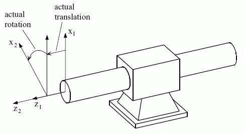
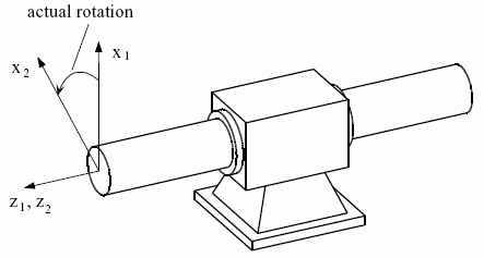
To measure the displacement and the angle of rotation, a frame is defined on each of the links such that the z-axes coincide and the positive directions agree. The distance of translation is defined as the distance required to translate the xy-plane of the first pair frame in the positive direction of the common z-axis until it coincides with the xy-plane of the second pair frame. The angle of rotation is defined as the angle required to rotate the x-axis of the first pair frame in the positive direction around the common z-axis until its direction coincides with the direction of the x-axis of the second pair frame.
EXPRESS specification:
            *)

            ENTITY cylindrical_pair

              SUBTYPE OF (low_order_kinematic_pair);
DERIVE

              SELF\low_order_kinematic_pair.t_x : BOOLEAN := FALSE;

              SELF\low_order_kinematic_pair.t_y : BOOLEAN := FALSE;

              SELF\low_order_kinematic_pair.t_z : BOOLEAN := TRUE;

              SELF\low_order_kinematic_pair.r_x : BOOLEAN := FALSE;

              SELF\low_order_kinematic_pair.r_y : BOOLEAN := FALSE;

              SELF\low_order_kinematic_pair.r_z : BOOLEAN := TRUE;

            END_ENTITY;
(*
Attribute definitions:
t_x: translation along the x-axis is constraint.
t_y: translation along the y-axis is constraint.
t_z: translation along the z-axis is not constraint.
r_x: rotation around the x-axis is constraint.
r_y: rotation around the y-axis is constraint.
r_z: rotation around the z-axis is not constraint.

EXPRESS specification:
            *)

            ENTITY cylindrical_pair_with_range

              SUBTYPE OF (cylindrical_pair);


              lower_limit_actual_translation :
            OPTIONAL
            length_measure;


              upper_limit_actual_translation :
            OPTIONAL
            length_measure;


              lower_limit_actual_rotation :
            OPTIONAL
            plane_angle_measure;


              upper_limit_actual_rotation :
            OPTIONAL
            plane_angle_measure;
WHERE

              WR1: (NOT EXISTS(lower_limit_actual_translation)
            OR
            NOT EXISTS(upper_limit_actual_translation))
            XOR
            (lower_limit_actual_translation < upper_limit_actual_translation);

              WR2: (NOT EXISTS(lower_limit_actual_rotation)
            OR
            NOT EXISTS(upper_limit_actual_rotation))
            XOR
            (lower_limit_actual_rotation < upper_limit_actual_rotation);

            END_ENTITY;
(*
Attribute definitions:
lower_limit_actual_translation: the minimum value of translation for the cylindrical_pair. The value of this attribute need not be specified.
upper_limit_actual_translation: the maximum value of translation for the cylindrical_pair. The value of this attribute need not be specified.
lower_limit_actual_rotation: the minimum value of rotation for the cylindrical_pair. The value of this attribute need not be specified.
upper_limit_actual_rotation: the maximum value of rotation for the cylindrical_pair. The value of this attribute need not be specified.
Formal propositions:
WR1: The range of translation of the cylindrical_pair shall be positive when both bounds are not given as unlimited.
WR2: The range of rotation of the cylindrical_pair shall be positive when both bounds are not given as unlimited.

NOTE 1 The fully_constrained_pair may be helpful in early design stages or for kinematic analysis systems, because it allows to fix two links each to the other without changing the topological structure.
NOTE 2 The concepts of pair value and pair range are not applicable to a fully_constrained_pair.
EXPRESS specification:
            *)

            ENTITY fully_constrained_pair

              SUBTYPE OF (low_order_kinematic_pair);
DERIVE

              SELF\low_order_kinematic_pair.t_x : BOOLEAN := FALSE;

              SELF\low_order_kinematic_pair.t_y : BOOLEAN := FALSE;

              SELF\low_order_kinematic_pair.t_z : BOOLEAN := FALSE;

              SELF\low_order_kinematic_pair.r_x : BOOLEAN := FALSE;

              SELF\low_order_kinematic_pair.r_y : BOOLEAN := FALSE;

              SELF\low_order_kinematic_pair.r_z : BOOLEAN := FALSE;

            END_ENTITY;
(*
Attribute definitions:
t_x: translation along the x-axis is constraint.
t_y: translation along the y-axis is constraint.
t_z: translation along the z-axis is constraint.
r_x: rotation around the x-axis is constraint.
r_y: rotation around the y-axis is constraint.
r_z: rotation around the z-axis is constraint.

To measure the motion of the second link with respect to the first link, a frame is defined on each of the links such that the origin lies in the center of the rolling circle of the respective link.
NOTE 1 See Figure 5, where different values of the constants "bevel", "helical_angle", and "gear_ratio" are shown. The lower gear always represents the first link; the upper gear is the second link.
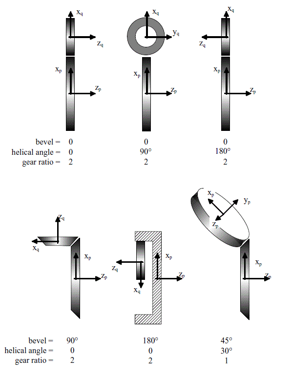
The direction of the z-axis is perpendicular to the plane of the circle. In a reference situation (with both rotation values being zero) the x-axis of the first link points from the origin towards the point of contact with the second link, while on the second link the x-axis points away from the point of contact.
Motion is measured in terms of the rotation of the contact point about the z-axis of the first link. The motion of the second link results from an analysis of the rolling process. At any instance the motion of the second link may be considered as a rotation of the second gear axis about the first gear axis while maintaining the distance (sum of the radii), the bevel, and the helical angle plus a rotation of the second gear about its own axis according to:

Thus absolute bevel values between 0 and π/2 represent external gears while absolute bevel values between π/2 and π represent internal gears.
The angle between the two x-axis directions is given by the bevel according to

with bevel ∈ ]-π,π],
where in case of cos(bevel) = 0, the sign of the bevel is defined according to:

The angle between the two y-axis directions is given by the helical angle according to:

with helical_angle ∈ ]-π,π],
where in case of cos(helical_angle) = 0, the sign of the helical angle is defined according to:

NOTE 2 In some cases the gear ratio depends on the radii of the rolling circles and also on the characteristics of the gear toothing such as in worm gears. For this reason the gear ratio is defined and not derived from the ratio of the two radii. Hence, the two radii are used to determine the geometrical arrangement of the two gears relative to each other in conjunction with bevel and helical angle, while the gear ratio determines the ratio of the second gear motion with respect to the rotation of the contact point about the first gear axis.
One way to construct the geometrical arrangement of the second gear relative to the first one is as follows:
An auxiliary frame is introduced at the point of contact with its axes xa, ya, and za all parallel to the respective axes of the first link frame. Now the auxiliary frame is rotated by the angle bevel about its ya-axis followed by a rotation by the helical angle about the (previously rotated) xa-axis. Now the xa-ya-plane represents the plane in which the second gear lies.
EXPRESS specification:
            *)

            ENTITY gear_pair

              SUBTYPE OF (low_order_kinematic_pair_with_motion_coupling);


              radius_first_link : length_measure;


              radius_second_link : length_measure;


              bevel : plane_angle_measure;


              helical_angle : plane_angle_measure;


              gear_ratio : REAL;
WHERE

              WR1: SIZEOF( QUERY(lr <* SELF\kinematic_pair.associated_link_representations_1 |
            NOT('KINEMATIC_STRUCTURE_SCHEMA.RIGID_LINK_REPRESENTATION' IN TYPEOF(lr)))) = 0;

            END_ENTITY;
(*
Attribute definitions:
radius_first_link: the radius of the rolling circle of the first link.
radius_second_link: the radius of the rolling circle of the second link.
bevel: the angle between the two x-axes.
helical_angle: the angle between the two y-axes.
gear_ratio: the gear ratio of the pair.
Formal propositions:
WR1: a gear_pair shall only be referenced by pair_representation_relationships with a rep_1 of type rigid_link_representation.

EXPRESS specification:
            *)

            ENTITY gear_pair_with_range

              SUBTYPE OF (gear_pair);


              lower_limit_actual_rotation_1 :
            OPTIONAL
            plane_angle_measure;


              upper_limit_actual_rotation_1 :
            OPTIONAL
            plane_angle_measure;
WHERE

              WR1: (NOT EXISTS(lower_limit_actual_rotation_1)
            OR
            NOT EXISTS(upper_limit_actual_rotation_1))
            XOR
            (lower_limit_actual_rotation_1 < upper_limit_actual_rotation_1);

            END_ENTITY;
(*
Attribute definitions:
lower_limit_actual_rotation_1: the minimum value of the pair parameter of the first link. The value of this attribute need not be specified.
upper_limit_actual_rotation_1: the maximum value of the pair parameter of the first link. The value of this attribute need not be specified.
Formal propositions:
WR1: The range of rotation of the gear_pair shall be positive when both bounds are not given as unlimited.

EXPRESS specification:
            *)

            ENTITY high_order_kinematic_pair

              ABSTRACT SUPERTYPE

            OF (ONEOF (linear_flexible_and_planar_curve_pair,
                                point_on_surface_pair,
                                point_on_planar_curve_pair,
                                planar_curve_pair,
                                surface_pair))

              SUBTYPE OF (kinematic_pair);
WHERE

              WR1: SIZEOF( QUERY(lr <* SELF\kinematic_pair.associated_link_representations_2 |
            NOT('KINEMATIC_STRUCTURE_SCHEMA.RIGID_LINK_REPRESENTATION' IN TYPEOF(lr)))) = 0;

            END_ENTITY;
(*
Formal propositions:
WR1: a high_order_kinematic_pair shall only be referenced by pair_representation_relationships with a rep_1 of type rigid_link_representation.

EXPRESS specification:
            *)

            ENTITY homokinetic_pair

              SUBTYPE OF (universal_pair);
WHERE

              WR1: NOT EXISTS(SELF.input_skew_angle);

            END_ENTITY;
(*
Formal propositions:
WR1: The input_skew_angle shall be omitted.

EXPRESS specification:
            *)

            ENTITY kinematic_link_representation

              ABSTRACT SUPERTYPE

            OF (ONEOF (linear_flexible_link_representation,
                                rigid_link_representation))

              SUBTYPE OF (representation);


              SELF\representation.context_of_items : geometric_representation_context;


              SELF\representation.items : SET[1:?] OF kinematic_link_representation_items;


              represented_link : kinematic_link;
INVERSE

              associated_shape_representation : SET[0:1] OF kinematic_link_representation_association FOR rep_1;

            END_ENTITY;
(*
Attribute definitions:
context_of_items: the geometric_representation_context providing the context for the items.
items: an inherited attribute that shall be of type kinematic_link_representation_items. There shall exist at least one kinematic_link_representation_items for the kinematic_link_representation.
represented_link: the link frame of the related kinematic_link.
associated_shape_representation: specifies an inverse relationship that specifies that the existence of the kinematic_link_representation is dependent on the existence of the kinematic_link_representation_association that specifies the kinematic_link_representation as its rep_1. There shall exist zero or one kinematic_link_representation_association for the kinematic_link_representation.

NOTE A kinematic_link_representation_association is used to define the shape of a link by associating a shape_representation to the corresponding kinematic_link_representation.
EXPRESS specification:
            *)

            ENTITY kinematic_link_representation_association

              SUBTYPE OF (representation_relationship);


              SELF\representation_relationship.rep_1 : kinematic_link_representation;


              SELF\representation_relationship.rep_2 : shape_representation;
WHERE

              WR1: (SELF\representation_relationship.rep_2.context_of_items :=:
            SELF\representation_relationship.rep_1.context_of_items) OR
            ('REPRESENTATION_SCHEMA.REPRESENTATION_RELATIONSHIP_WITH_TRANSFORMATION' IN TYPEOF(SELF));

            END_ENTITY;
(*
Attribute definitions:
rep_1: the kinematic_link_representation with which rep_2 is associated.
rep_2: the shape_representation with which rep_1 is associated.
Formal propositions:
WR1: The context_of_items of rep_2 shall be identical to the link frame of the kinematic_link_representation with which rep_2 is associated.

EXPRESS specification:
            *)

            ENTITY kinematic_pair

              ABSTRACT SUPERTYPE

            OF (ONEOF (high_order_kinematic_pair,
                                low_order_kinematic_pair_with_motion_coupling,
                                low_order_kinematic_pair)
                        ANDOR actuated_kinematic_pair)

              SUBTYPE OF (geometric_representation_item, item_defined_transformation);


              joint : kinematic_joint;


              SELF\item_defined_transformation.transform_item_1 : rigid_placement;


              SELF\item_defined_transformation.transform_item_2 : rigid_placement;
DERIVE

              associated_link_representations_1 : SET[1:?] OF kinematic_link_representation := sort_link_associations(link_representation_associations, TRUE);

              associated_link_representations_2 : SET[1:?] OF kinematic_link_representation := sort_link_associations(link_representation_associations, FALSE);

              SELF\item_defined_transformation.name : label := SELF\representation_item.name;
INVERSE

              link_representation_associations : SET[1:?] OF pair_representation_relationship FOR transformation_operator;

            END_ENTITY;
(*
Attribute definitions:
joint: the joint whose motion is constrained by the kinematic_pair.
transform_item_1: the placement of the pair frame on the first link in the context of the first link, i.e., its link frame.
transform_item_2: the placement of the pair frame on the second link in the context of the second link, i.e., its link frame.
associated_link_representations_1: identifies the first kinematic_link_representation that corresponds to the edge_start of the referenced kinematic_joint.
associated_link_representations_2: identifies the second kinematic_link_representation that corresponds to the edge_end of the referenced kinematic_joint.
name: the inherited attribute name from item_defined_transformation is re-declared as derived and assigned the same value as the inherited attribute name from representation_item.
link_representation_associations: the inverse references of kinematic_pair by pair_representation_relationship. There shall be at least one reference.

EXPRESS specification:
            *)

            ENTITY linear_flexible_and_pinion_pair

              SUBTYPE OF (low_order_kinematic_pair_with_motion_coupling);


              pinion_radius : length_measure;
WHERE

              WR1: SIZEOF( QUERY(lr <* SELF\kinematic_pair.associated_link_representations_1 |
            NOT('KINEMATIC_STRUCTURE_SCHEMA.LINEAR_FLEXIBLE_LINK_REPRESENTATION' IN TYPEOF(lr)))) = 0;

            END_ENTITY;
(*
Attribute definitions:
pinion_radius: the radius of the rolling circle of the pinion.
Formal propositions:
WR1: All elements in the inherited attribute associated_link_representations_1 shall be of type linear_flexible_link_representation.

EXPRESS specification:
            *)

            ENTITY linear_flexible_and_planar_curve_pair

              SUBTYPE OF (high_order_kinematic_pair);


              pair_curve : curve;


              orientation : BOOLEAN;
WHERE

              WR1: SIZEOF( QUERY(r <* SELF\kinematic_pair.associated_link_representations_1 | NOT(pair_curve IN r.items))) = 0;

              WR2: SIZEOF( QUERY(lr <* SELF\kinematic_pair.associated_link_representations_1 |
            NOT('KINEMATIC_STRUCTURE_SCHEMA.LINEAR_FLEXIBLE_LINK_REPRESENTATION' IN TYPEOF(lr)))) = 0;

            END_ENTITY;
(*
Attribute definitions:
pair_curve: the planar curve on the first link of the pair along which the second linear flexible link is sliding.
orientation: a flag indicating whether the x-axis-directions agree.
Formal propositions:
WR1: The curve referenced by pair_curve shall be a member of associated_link_representations_1.
WR2: All elements in the inherited attribute associated_link_representations_1 shall be of type linear_flexible_link_representation.

EXPRESS specification:
            *)

            ENTITY linear_flexible_link_representation

              SUBTYPE OF (kinematic_link_representation);

            END_ENTITY;
(*

EXPRESS specification:
            *)

            ENTITY low_order_kinematic_pair

              SUPERTYPE OF (ONEOF (revolute_pair,
                       cylindrical_pair,
                       spherical_pair,
                       spherical_pair_with_pin,
                       planar_pair,
                       unconstrained_pair,
                       fully_constrained_pair,
                       prismatic_pair,
                       universal_pair,
                       low_order_kinematic_pair_with_range))

              SUBTYPE OF (kinematic_pair);


              t_x : BOOLEAN;


              t_y : BOOLEAN;


              t_z : BOOLEAN;


              r_x : BOOLEAN;


              r_y : BOOLEAN;


              r_z : BOOLEAN;
WHERE

              WR1: SIZEOF( QUERY(lr <* SELF\kinematic_pair.associated_link_representations_1 |
            NOT('KINEMATIC_STRUCTURE_SCHEMA.RIGID_LINK_REPRESENTATION' IN TYPEOF(lr)))) = 0;

              WR2: SIZEOF( QUERY(lr <* SELF\kinematic_pair.associated_link_representations_2 |
            NOT('KINEMATIC_STRUCTURE_SCHEMA.RIGID_LINK_REPRESENTATION' IN TYPEOF(lr)))) = 0;

            END_ENTITY;
(*
Attribute definitions:
t_x: translation along the x-axis; a TRUE value indicates that it is not constraint.
t_y: translation along the y-axis; a TRUE value indicates that it is not constraint.
t_z: translation along the z-axis; a TRUE value indicates that it is not constraint.
r_x: rotation around the x-axis; a TRUE value indicates that it is not constraint.
r_y: rotation around the y-axis; a TRUE value indicates that it is not constraint.
r_z: rotation around the z-axis; a TRUE value indicates that it is not constraint.
Formal propositions:
WR1: All elements in the inherited attribute associated_link_representations_1 shall be of type rigid_link_representation.
WR2: All elements in the inherited attribute associated_link_representations_2 shall be of type rigid_link_representation.

EXPRESS specification:
            *)

            ENTITY low_order_kinematic_pair_with_motion_coupling

              ABSTRACT SUPERTYPE

            OF (ONEOF (gear_pair,
                                linear_flexible_and_pinion_pair,
                                rack_and_pinion_pair,
                                screw_pair))

              SUBTYPE OF (kinematic_pair);
WHERE

              WR1: SIZEOF( QUERY(lr <* SELF\kinematic_pair.associated_link_representations_2 |
            NOT('KINEMATIC_STRUCTURE_SCHEMA.RIGID_LINK_REPRESENTATION' IN TYPEOF(lr)))) = 0;

            END_ENTITY;
(*
Formal propositions:
WR1: All elements in the inherited attribute associated_link_representations_2 shall be of type rigid_link_representation.

EXPRESS specification:
            *)

            ENTITY low_order_kinematic_pair_with_range

              SUBTYPE OF (low_order_kinematic_pair);


              lower_limit_actual_rotation_x :
            OPTIONAL
            plane_angle_measure;


              upper_limit_actual_rotation_x :
            OPTIONAL
            plane_angle_measure;


              lower_limit_actual_rotation_y :
            OPTIONAL
            plane_angle_measure;


              upper_limit_actual_rotation_y :
            OPTIONAL
            plane_angle_measure;


              lower_limit_actual_rotation_z :
            OPTIONAL
            plane_angle_measure;


              upper_limit_actual_rotation_z :
            OPTIONAL
            plane_angle_measure;


              lower_limit_actual_translation_x :
            OPTIONAL
            length_measure;


              upper_limit_actual_translation_x :
            OPTIONAL
            length_measure;


              lower_limit_actual_translation_y :
            OPTIONAL
            length_measure;


              upper_limit_actual_translation_y :
            OPTIONAL
            length_measure;


              lower_limit_actual_translation_z :
            OPTIONAL
            length_measure;


              upper_limit_actual_translation_z :
            OPTIONAL
            length_measure;

            END_ENTITY;
(*
Attribute definitions:
lower_limit_actual_rotation_x: the minimum value of the yaw angle for the low_order_kinematic_pair. The value of this attribute need not be specified.
upper_limit_actual_rotation_x: the maximum value of the yaw angle for the low_order_kinematic_pair. The value of this attribute need not be specified.
lower_limit_actual_rotation_y: the minimum value of the pitch angle for the low_order_kinematic_pair. The value of this attribute need not be specified.
upper_limit_actual_rotation_y: the maximum value of the pitch angle for the low_order_kinematic_pair. The value of this attribute need not be specified.
lower_limit_actual_rotation_z: the minimum value of the roll angle for the low_order_kinematic_pair. The value of this attribute need not be specified.
upper_limit_actual_rotation_z: the maximum value of the roll angle for the low_order_kinematic_pair. The value of this attribute need not be specified.
lower_limit_actual_translation_x: the minimum value of translation in x-direction for the low_order_kinematic_pair. The value of this attribute need not be specified.
upper_limit_actual_translation_x: the maximum value of translation in x-direction for the low_order_kinematic_pair. The value of this attribute need not be specified.
lower_limit_actual_translation_y: the minimum value of translation in y-direction for the low_order_kinematic_pair. The value of this attribute need not be specified.
upper_limit_actual_translation_y: the maximum value of translation in y-direction for the low_order_kinematic_pair. The value of this attribute need not be specified.
lower_limit_actual_translation_z: the minimum value of translation in z-direction for the low_order_kinematic_pair. The value of this attribute need not be specified.
upper_limit_actual_translation_z: the maximum value of translation in z-direction for the low_order_kinematic_pair. The value of this attribute need not be specified.

EXPRESS specification:
            *)

            ENTITY mechanism_representation

              SUBTYPE OF (representation);


              SELF\representation.context_of_items : geometric_representation_context;


              SELF\representation.items : SET[1:?] OF pair_representation_relationship;


              represented_topology : kinematic_topology_representation_select;
DERIVE

              represented_joints : SET[1:?] OF kinematic_joint := collect_joints(items);
WHERE

              WR1: (('KINEMATIC_TOPOLOGY_SCHEMA.KINEMATIC_TOPOLOGY_STRUCTURE' IN TYPEOF(represented_topology))
            AND (represented_joints :=: represented_topology.items)) OR
            (('KINEMATIC_TOPOLOGY_SCHEMA.KINEMATIC_TOPOLOGY_DIRECTED_STRUCTURE' IN TYPEOF(represented_topology))
            AND (represented_joints :=: get_kinematic_joints_from_oriented_joints(represented_topology.items))) OR
            (('KINEMATIC_TOPOLOGY_SCHEMA.KINEMATIC_TOPOLOGY_NETWORK_STRUCTURE' IN TYPEOF(represented_topology))
            AND (represented_joints :=: get_kinematic_joints_from_kinematic_loops(represented_topology.items)));

            END_ENTITY;
(*
Attribute definitions:
context_of_items: an inherited attribute that shall be of type geometric_representation_context.
items: an inherited attribute that shall be of type pair_representation_relationship. There shall exist at least one pair_representation_relationship for the mechanism_representation.
represented_topology: the represented kinematic_topology_representation_select.
represented_joints: the represented kinematic_joints.
Formal propositions:
WR1: The mechanism_representation shall provide exactly one pair of pair_representation_relationship and kinematic_pair for each kinematic_joint of the represented_topology.

EXPRESS specification:
            *)

            ENTITY pair_representation_relationship

              SUBTYPE OF (geometric_representation_item, representation_relationship_with_transformation);


              SELF\representation_relationship.rep_1 : kinematic_link_representation;


              SELF\representation_relationship.rep_2 : kinematic_link_representation;


              SELF\representation_relationship_with_transformation.transformation_operator : kinematic_pair;
WHERE

              WR1: transformation_operator\item_defined_transformation.transform_item_1 IN rep_1.items;

              WR2: transformation_operator\item_defined_transformation.transform_item_2 IN rep_2.items;

              WR3: rep_1\kinematic_link_representation.represented_link = transformation_operator\kinematic_pair.joint.edge_start;

              WR4: rep_2\kinematic_link_representation.represented_link = transformation_operator\kinematic_pair.joint.edge_end;

            END_ENTITY;
(*
Attribute definitions:
rep_1: an inherited attribute shall be of type kinematic_link_representation.
rep_2: an inherited attribute shall be of type rigid_link_representation.
transformation_operator: an inherited attribute shall be of type kinematic_pair.
Formal propositions:
WR1: The rigid_placement referenced by the chain transformation_operator and transform_item_1 shall be an element in the items of rep_1.
WR2: The rigid_placement referenced by the chain transformation_operator and transform_item_2 shall be an element in the items of rep_2.
WR3: The represented_link of rep_1 shall be the same as the one referenced by the chain transformation_operator, joint and edge_start.
WR4: The represented_link of rep_2 shall be the same as the one referenced by the chain transformation_operator, joint and edge_end.


The following notation is used:
NOTE 1 See Figure 6 for an exploded view of a curve pair. In this case orientation is FALSE, as the x-axes have opposite directions.
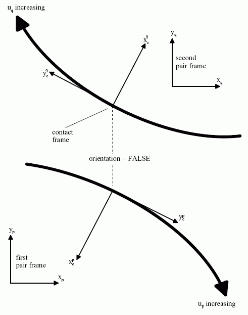
The following equations apply to sliding_curve_pair and rolling_curve_pair.
The contact frame is determined from both sides of the pair as follows, beginning with the second link:
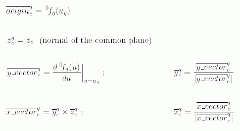

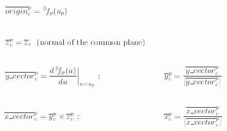
and the three direction vectors

may be used to establish the rigid homogeneous matrix representation of the placement of the contact frame qPFc relative to the second pair frame.
NOTE 2 See Figure 7 for an illustration of the relationships between the frames.
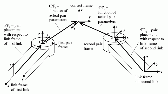
The same analysis is performed for the first link.
The contact point shall be identically positioned, relative to the world coordinate system, irrespective of whether it is approached from the second or the first link.

The z-directions are all normal to the same plane; hence

At this stage, the direction vectors

are either

In case 1, orientation is TRUE and both x-directions are identical.
In case 2, orientation is FALSE and xcp (as well as ycp) is rotated by π about the zc direction.
EXPRESS specification:
            *)

            ENTITY planar_curve_pair

              SUPERTYPE OF (ONEOF (sliding_curve_pair,
                       rolling_curve_pair)
               ANDOR planar_curve_pair_range)

              SUBTYPE OF (high_order_kinematic_pair);


              curve_1 : curve;


              curve_2 : curve;


              orientation : BOOLEAN;
WHERE

              WR1: SIZEOF( QUERY(r <* SELF\kinematic_pair.associated_link_representations_1 | NOT(curve_1 IN r.items))) = 0;

              WR2: SIZEOF( QUERY(r <* SELF\kinematic_pair.associated_link_representations_2 | NOT(curve_2 IN r.items))) = 0;

              WR3: SIZEOF( QUERY(lr <* SELF\kinematic_pair.associated_link_representations_1 |
            NOT('KINEMATIC_STRUCTURE_SCHEMA.RIGID_LINK_REPRESENTATION' IN TYPEOF(lr)))) = 0;

            END_ENTITY;
(*
Attribute definitions:
curve_1: the contact curve on the first link, defined in the coordinate system. This curve shall lie within a plane.
curve_2: the contact curve on the second link, defined in the coordinate system. This curve shall lie within a plane.
orientation: a flag indicating whether the x-axis-directions agree.
Formal propositions:
WR1: The curve referenced by curve_1 shall be a member of all associated_link_representations_1.
WR2: The curve referenced by curve_2 shall be a member of all associated_link_representations_2.
WR3: All elements in the inherited attribute associated_link_representations_1 shall be of type rigid_link_representation.
Informal propositions:
IP1: The curves used as curve_1 and curve_2 shall be planar curves.
IP2: The curves used as curve_1 and curve_2 shall be smooth in their entire domain, and their tangent vectors shall change their direction only in a steady manner, regardless of whether the curves are composite or not.
NOTE 3 This is equivalent to requiring curve_1 and curve_2 to be G1 continuous throughout and that, in the case of a composite_curve, the transition_code shall be at least cont_same_gradient at each segment junction point.
IP3: If the directions xq and xcp are identical, the orientation shall be TRUE. If the directions xq and xcp are oriented in the opposite direction, the orientation shall be FALSE.

EXPRESS specification:
            *)

            ENTITY planar_curve_pair_range

              SUBTYPE OF (planar_curve_pair);


              range_on_curve_1 : trimmed_curve;


              range_on_curve_2 : trimmed_curve;
WHERE

              WR1: SELF\planar_curve_pair.curve_1 :=: range_on_curve_1.basis_curve;

              WR2: SELF\planar_curve_pair.curve_2 :=: range_on_curve_2.basis_curve;

              WR3: SIZEOF( QUERY(r <* SELF\kinematic_pair.associated_link_representations_1 | NOT(range_on_curve_1 IN r.items))) = 0;

              WR4: SIZEOF( QUERY(r <* SELF\kinematic_pair.associated_link_representations_2 | NOT(range_on_curve_2 IN r.items))) = 0;

            END_ENTITY;
(*
Attribute definitions:
range_on_curve_1: the admissible range for the positional pair parameter value on the curve on the first link of the pair.
range_on_curve_2: the admissible range for the positional pair parameter value on the curve on the second link of the pair.
Formal propositions:
WR1: The basis_curve of range_on_curve_1 shall be the same as curve_1.
WR2: The basis_curve of range_on_curve_2 shall be the same as curve_2.
WR3: The curve referenced by range_on_curve_1 shall be a member of associated_link_representations_1.
WR4: The curve referenced by range_on_curve_2 shall be a member of associated_link_representations_2.

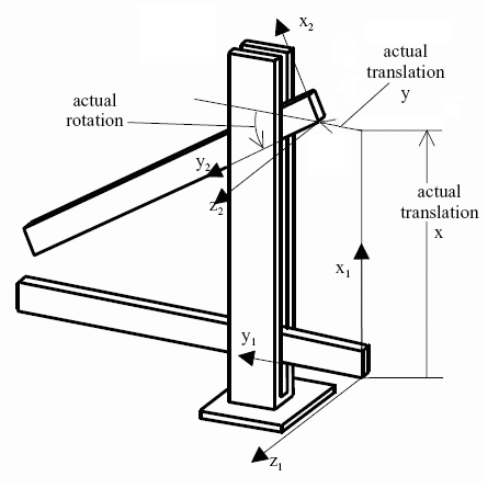
NOTE See Figure 8.
EXPRESS specification:
            *)

            ENTITY planar_pair

              SUBTYPE OF (low_order_kinematic_pair);
DERIVE

              SELF\low_order_kinematic_pair.t_x : BOOLEAN := TRUE;

              SELF\low_order_kinematic_pair.t_y : BOOLEAN := TRUE;

              SELF\low_order_kinematic_pair.t_z : BOOLEAN := FALSE;

              SELF\low_order_kinematic_pair.r_x : BOOLEAN := FALSE;

              SELF\low_order_kinematic_pair.r_y : BOOLEAN := FALSE;

              SELF\low_order_kinematic_pair.r_z : BOOLEAN := TRUE;

            END_ENTITY;
(*
Attribute definitions:
t_x: translation along the x-axis is not constraint.
t_y: translation along the y-axis is not constraint.
t_z: translation along the z-axis is constraint.
r_x: rotation around the x-axis is constraint.
r_y: rotation around the y-axis is constraint.
r_z: rotation around the z-axis is not constraint.

EXPRESS specification:
            *)

            ENTITY planar_pair_with_range

              SUBTYPE OF (planar_pair);


              lower_limit_actual_rotation :
            OPTIONAL
            plane_angle_measure;


              upper_limit_actual_rotation :
            OPTIONAL
            plane_angle_measure;


              lower_limit_actual_translation_x :
            OPTIONAL
            length_measure;


              upper_limit_actual_translation_x :
            OPTIONAL
            length_measure;


              lower_limit_actual_translation_y :
            OPTIONAL
            length_measure;


              upper_limit_actual_translation_y :
            OPTIONAL
            length_measure;
WHERE

              WR1: (NOT EXISTS(lower_limit_actual_rotation)
            OR
            NOT EXISTS(upper_limit_actual_rotation))
            XOR
            (lower_limit_actual_rotation < upper_limit_actual_rotation);

              WR2: (NOT EXISTS(lower_limit_actual_translation_x)
            OR
            NOT EXISTS(upper_limit_actual_translation_x))
            XOR
            (lower_limit_actual_translation_x < upper_limit_actual_translation_x);

              WR3: (NOT EXISTS(lower_limit_actual_translation_y)
            OR
            NOT EXISTS(upper_limit_actual_translation_y))
            XOR
            (lower_limit_actual_translation_y < upper_limit_actual_translation_y);

            END_ENTITY;
(*
Attribute definitions:
lower_limit_actual_rotation: the minimum value of the angle of rotation for the planar_pair. The value of this attribute need not be specified.
upper_limit_actual_rotation: the maximum value of the angle of rotation for the planar_pair. The value of this attribute need not be specified.
lower_limit_actual_translation_x: the minimum value of translation in x-direction for the planar_pair. The value of this attribute need not be specified.
upper_limit_actual_translation_x: the maximum value of translation in x-direction for the planar_pair. The value of this attribute need not be specified.
lower_limit_actual_translation_y: the minimum value of translation in y-direction for the planar_pair. The value of this attribute need not be specified.
upper_limit_actual_translation_y: the maximum value of translation in y-direction for the planar_pair. The value of this attribute need not be specified.
Formal propositions:
WR1: The range of rotation of the planar_pair shall be positive when both bounds are not given as unlimited.
WR2: The range of translation in x-direction of the planar_pair shall be positive when both bounds are not given as unlimited.
WR3: The range of translation in y-direction of the planar_pair shall be positive when both bounds are not given as unlimited.

NOTE 1 Translational motion of the second link is constrained to the one-dimensional parameter space of the curve, while its rotational motion about the contact point is not constrained. Therefore, a point_on_planar_curve_pair behaves like a spherical_pair that additionally may move along a curve on the first link.
The contact point specifies the origin of a frame called the contact frame. The x-axis of the contact frame is parallel to the tangent to the curve in the contact point and points into the direction where the curve parameter increases. The y-axis of the contact frame is normal to the plane in which the curve is defined. Hence, the z-axis of the contact frame coincides with a local normal to the curve which lies in the plane of the curve and passes the contact point.
NOTE 2 See Figure 9. In this case orientation is TRUE, as the yc1-axis has the same direction as the z1-axis.
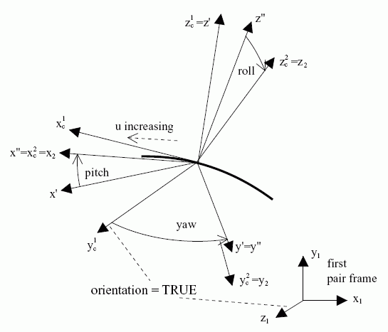
To support the measure of motion, a pair frame is defined on each of the links. The representation ƒ(u) of the two-dimensional curve is given in the xy-plane of the pair frame on the first link. Therefore, the z-axis of this pair frame always serves as the normal to the plane of the curve.
NOTE 3 The definition of the curve plane and of its normal as specified here becomes important for cases where the curve is a straight line.
The translational motion is given by the actual curve parameter of the contact point, u1. The three angles of rotation are defined as the yaw, pitch, and roll angles. They are required to rotate the x-, y-, and z-axes of the contact frame until its directions coincide with the axis directions of the second pair frame.
The origin of the pair frame on the second link coincides with the contact point, and the axes of this pair frame agree with the axes of the contact frame when all three rotations have been performed.
The following notation is used in the subsequent specification:
In order to migrate from the first pair frame to the second pair frame, the following sequence of transformations has to be performed:


EXPRESS specification:
            *)

            ENTITY point_on_planar_curve_pair

              SUBTYPE OF (high_order_kinematic_pair);


              pair_curve : curve;


              orientation : BOOLEAN;
WHERE

              WR1: SIZEOF( QUERY(r <* SELF\kinematic_pair.associated_link_representations_1 | NOT(pair_curve IN r.items))) = 0;

              WR2: SIZEOF( QUERY(lr <* SELF\kinematic_pair.associated_link_representations_1 |
            NOT('KINEMATIC_STRUCTURE_SCHEMA.RIGID_LINK_REPRESENTATION' IN TYPEOF(lr)))) = 0;

            END_ENTITY;
(*
Attribute definitions:
pair_curve: the planar curve on the first link of the pair on which the point on the second link is sliding.
orientation: a flag indicating whether the y-axis of the unrotated contact frame agrees with the z-axis of the pair frame on the first link.
Formal propositions:
WR1: The curve referenced by pair_curve shall be a member of associated_link_representations_1.
WR2: All elements in the inherited attribute associated_link_representations_1 shall be of type rigid_link_representation.
Informal propositions:
IP1: The curve used as pair_curve shall be planar.
IP2: The curve used as pair_curve shall be smooth in its entire domain, and its tangent vector shall change its direction only in a steady manner, regardless of whether the curve is composed of multiple curves or not.
NOTE 4 This is equivalent to requiring the pair_curve to be G1 continuous throughout and that, in the case of a composite_curve, the transition_code shall be at least cont_same_gradient at each segment junction point.
IP3: If the directions z1 and yc1 are identical, the orientation shall be TRUE. If the directions z1 and yc1 are oriented in the opposite direction, the orientation shall be FALSE.

EXPRESS specification:
            *)

            ENTITY point_on_planar_curve_pair_with_range

              SUBTYPE OF (point_on_planar_curve_pair);


              range_on_pair_curve : trimmed_curve;


              lower_limit_yaw :
            OPTIONAL
            plane_angle_measure;


              upper_limit_yaw :
            OPTIONAL
            plane_angle_measure;


              lower_limit_pitch :
            OPTIONAL
            plane_angle_measure;


              upper_limit_pitch :
            OPTIONAL
            plane_angle_measure;


              lower_limit_roll :
            OPTIONAL
            plane_angle_measure;


              upper_limit_roll :
            OPTIONAL
            plane_angle_measure;
WHERE

              WR1: (NOT EXISTS(lower_limit_pitch)
            OR
            NOT EXISTS(upper_limit_pitch))
            XOR
            (lower_limit_pitch < upper_limit_pitch);

              WR2: (NOT EXISTS(lower_limit_yaw)
            OR
            NOT EXISTS(upper_limit_yaw))
            XOR
            (lower_limit_yaw < upper_limit_yaw);

              WR3: (NOT EXISTS(lower_limit_roll)
            OR
            NOT EXISTS(upper_limit_roll))
            XOR
            (lower_limit_roll < upper_limit_roll);

              WR4: SIZEOF( QUERY(r <* SELF\kinematic_pair.associated_link_representations_1 | NOT(range_on_pair_curve IN r.items))) = 0;

            END_ENTITY;
(*
Attribute definitions:
range_on_pair_curve: the admissible range for the positional pair parameter value on the contact curve on the first link.
lower_limit_yaw: the minimum value of the yaw angle for the point_on_planar_curve_pair. The value of this attribute need not be specified.
upper_limit_yaw: the maximum value of the yaw angle for the point_on_planar_curve_pair. The value of this attribute need not be specified.
lower_limit_pitch: the minimum value of the pitch angle for the point_on_planar_curve_pair. The value of this attribute need not be specified.
upper_limit_pitch: the maximum value of the pitch angle for the point_on_planar_curve_pair. The value of this attribute need not be specified.
lower_limit_roll: the minimum value of the roll angle for the point_on_planar_curve_pair. The value of this attribute need not be specified.
upper_limit_roll: the maximum value of the roll angle for the point_on_planar_curve_pair. The value of this attribute need not be specified.
Formal propositions:
WR1: The range of rotation about the x-axis of the point_on_planar_curve_pair shall be positive when both bounds are not given as unlimited.
WR2: The range of rotation about the y-axis of the point_on_planar_curve_pair shall be positive when both bounds are not given as unlimited.
WR3: The range of rotation about the z-axis of the point_on_planar_curve_pair shall be positive when both bounds are not given as unlimited.
WR4: The curve referenced by range_on_pair_curve shall be a member of associated_link_representations_1.

NOTE 1 Translational motion of the second link is constrained to the two-dimensional parameter space of the surface, while its rotational motion about the contact point is not constrained. Therefore, a point_on_surface_pair behaves like a spherical_pair that additionally may move along a surface on the first link.
NOTE 2 See Figure 10.
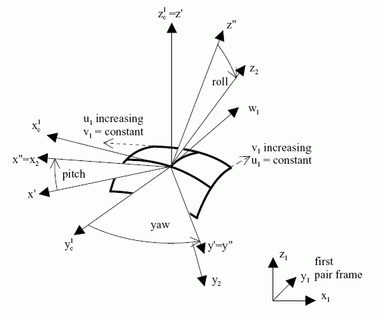
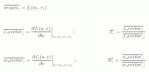
To support the measure of motion, a pair frame is defined on each of the links. The representation ƒ1(u, v) is defined relative to the pair frame on the first link. The translational motion is given by the actual surface parameters of the contact point, u1 and v1. The three angles of rotation are defined as the yaw, pitch, and roll angles. They are required to rotate the x-, y-, and z-axes of the contact frame until its directions coincide with the axis directions of the second pair frame. The origin of the pair frame on the second link coincides with the contact point. In order to migrate from the first pair frame to the second pair frame, the following sequence of transformations has to be performed:


EXPRESS specification:
            *)

            ENTITY point_on_surface_pair

              SUBTYPE OF (high_order_kinematic_pair);


              pair_surface : surface;
WHERE

              WR1: SIZEOF( QUERY(r <* SELF\kinematic_pair.associated_link_representations_1 | NOT(pair_surface IN r.items))) = 0;

              WR2: SIZEOF( QUERY(lr <* SELF\kinematic_pair.associated_link_representations_1 |
            NOT('KINEMATIC_STRUCTURE_SCHEMA.RIGID_LINK_REPRESENTATION' IN TYPEOF(lr)))) = 0;

            END_ENTITY;
(*
Attribute definitions:
pair_surface: the surface on the first link of the pair on which the point on the second link is sliding.
Formal propositions:
WR1: The surface referenced by pair_surface shall be an item of all associated_link_representations_1.
WR2: All elements in the inherited attribute associated_link_representations_1 shall be of type rigid_link_representation.
Informal propositions:
IP1: The surface used as pair_surface shall be smooth in its entire domain, and its tangent vectors shall change their direction only in a steady manner, regardless of whether the surface is composed of multiple surfaces or not.
NOTE 3 This is equivalent to requiring the pair_surface to be G1 continuous throughout and that, in the case of a rectangular_composite_surface, the transition_code shall be at least cont_same_gradient at each segment junction curve. (See ISO 10303-42.)

EXPRESS specification:
            *)

            ENTITY point_on_surface_pair_with_range

              SUBTYPE OF (point_on_surface_pair);


              range_on_pair_surface : rectangular_trimmed_surface;


              lower_limit_yaw :
            OPTIONAL
            plane_angle_measure;


              upper_limit_yaw :
            OPTIONAL
            plane_angle_measure;


              lower_limit_pitch :
            OPTIONAL
            plane_angle_measure;


              upper_limit_pitch :
            OPTIONAL
            plane_angle_measure;


              lower_limit_roll :
            OPTIONAL
            plane_angle_measure;


              upper_limit_roll :
            OPTIONAL
            plane_angle_measure;
WHERE

              WR1: (NOT EXISTS(lower_limit_pitch)
            OR
            NOT EXISTS(upper_limit_pitch))
            XOR
            (lower_limit_pitch < upper_limit_pitch);

              WR2: (NOT EXISTS(lower_limit_yaw)
            OR
            NOT EXISTS(upper_limit_yaw))
            XOR
            (lower_limit_yaw < upper_limit_yaw);

              WR3: (NOT EXISTS(lower_limit_roll)
            OR
            NOT EXISTS(upper_limit_roll))
            XOR
            (lower_limit_roll < upper_limit_roll);

              WR4: SIZEOF( QUERY(r <* SELF\kinematic_pair.associated_link_representations_1 | NOT(range_on_pair_surface IN r.items))) =
            0;

            END_ENTITY;
(*
Attribute definitions:
range_on_pair_surface: the admissible range for the positional pair parameter value on the contact surface on the first link.
lower_limit_yaw: the minimum value of the yaw angle for the point_on_surface_pair. The value of this attribute need not be specified.
upper_limit_yaw: the maximum value of the yaw angle for the point_on_surface_pair. The value of this attribute need not be specified.
lower_limit_pitch: the minimum value of the pitch angle for the point_on_surface_pair. The value of this attribute need not be specified.
upper_limit_pitch: the maximum value of the pitch angle for the point_on_surface_pair. The value of this attribute need not be specified.
lower_limit_roll: the minimum value of the roll angle for the point_on_surface_pair. The value of this attribute need not be specified.
upper_limit_roll: the maximum value of the roll angle for the point_on_surface_pair. The value of this attribute need not be specified.
Formal propositions:
WR1: The range of rotation about the x-axis of the point_on_surface_pair shall be positive when both bounds are not given as unlimited.
WR2: The range of rotation about the y-axis of the point_on_surface_pair shall be positive when both bounds are not given as unlimited.
WR3: The range of rotation about the z-axis of the point_on_surface_pair shall be positive when both bounds are not given as unlimited.
WR4: The surface referenced by range_on_pair_surface shall be a member of associated_link_representations_1.

NOTE See Figure 11.
EXPRESS specification:
            *)

            ENTITY prismatic_pair

              SUBTYPE OF (low_order_kinematic_pair);
DERIVE

              SELF\low_order_kinematic_pair.t_x : BOOLEAN := TRUE;

              SELF\low_order_kinematic_pair.t_y : BOOLEAN := FALSE;

              SELF\low_order_kinematic_pair.t_z : BOOLEAN := FALSE;

              SELF\low_order_kinematic_pair.r_x : BOOLEAN := FALSE;

              SELF\low_order_kinematic_pair.r_y : BOOLEAN := FALSE;

              SELF\low_order_kinematic_pair.r_z : BOOLEAN := FALSE;

            END_ENTITY;
(*
Attribute definitions:
t_x: translation along the x-axis is not constraint.
t_y: translation along the y-axis is constraint.
t_z: translation along the z-axis is constraint.
r_x: rotation around the x-axis is constraint.
r_y: rotation around the y-axis is constraint.
r_z: rotation around the z-axis is constraint.

EXPRESS specification:
            *)

            ENTITY prismatic_pair_with_range

              SUBTYPE OF (prismatic_pair);


              lower_limit_actual_translation :
            OPTIONAL
            length_measure;


              upper_limit_actual_translation :
            OPTIONAL
            length_measure;
WHERE

              WR1: (NOT EXISTS(lower_limit_actual_translation)
            OR
            NOT EXISTS(upper_limit_actual_translation))
            XOR
            (lower_limit_actual_translation < upper_limit_actual_translation);

            END_ENTITY;
(*
Attribute definitions:
lower_limit_actual_translation: the minimum value of the pair parameter. The value of this attribute need not be specified.
upper_limit_actual_translation: the maximum value of the pair parameter. The value of this attribute need not be specified.
Formal propositions:
WR1: The range of the prismatic_pair shall be positive when both bounds are not given as unlimited.

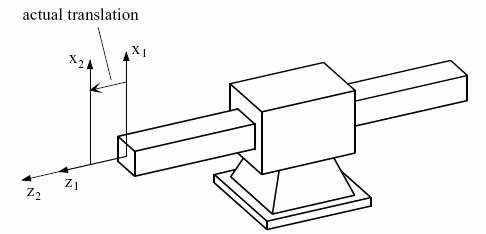
NOTE See Figure 12. The rack and pinion pair may be considered as a special case of the rolling_curve_pair with one curve being a straight line and the other a circle.
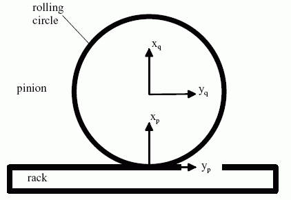
The rack is always the first link; the pinion is the second link. The rack_and_pinion_pair constrains the motion between two adjacent links to a translation along a common axis and a rotation about an axis perpendicular to it.
To measure the motion of the second link with respect to the first link, a frame is defined on each of the links. On the pinion, the origin is the center of the rolling circle. The direction of the z-axis on both rack and pinion is perpendicular to the plane of the circle.
In a reference situation (with both pair parameter values being zero), the x-axis of the pinion points from the origin away from the point of contact with the rack. In the same reference situation, the x-axis of the rack points from the point of contact towards the center of the pinion. Motion is measured in terms of the translation of the contact point along the y-axis of the rack (first link). The motion of the second link results from an analysis of the rolling process. At any instance the motion of the second link is composed of a translation and a rotation where the rotation part is calculated from:

EXPRESS specification:
            *)

            ENTITY rack_and_pinion_pair

              SUBTYPE OF (low_order_kinematic_pair_with_motion_coupling);


              pinion_radius : length_measure;
WHERE

              WR1: SIZEOF( QUERY(lr <* SELF\kinematic_pair.associated_link_representations_1 |
            NOT('KINEMATIC_STRUCTURE_SCHEMA.RIGID_LINK_REPRESENTATION' IN TYPEOF(lr)))) = 0;

            END_ENTITY;
(*
Attribute definitions:
pinion_radius: the radius of the rolling circle of the pinion.
Formal propositions:
WR1: All elements in the inherited attribute associated_link_representations_1 shall be of type rigid_link_representation.

EXPRESS specification:
            *)

            ENTITY rack_and_pinion_pair_with_range

              SUBTYPE OF (rack_and_pinion_pair);


              lower_limit_rack_displacement :
            OPTIONAL
            length_measure;


              upper_limit_rack_displacement :
            OPTIONAL
            length_measure;
WHERE

              WR1: (NOT EXISTS(lower_limit_rack_displacement)
            OR
            NOT EXISTS(upper_limit_rack_displacement))
            XOR
            (lower_limit_rack_displacement < upper_limit_rack_displacement);

            END_ENTITY;
(*
Attribute definitions:
lower_limit_rack_displacement: the minimum value of the pair parameter for the rack. The value of this attribute need not be specified.
upper_limit_rack_displacement: the maximum value of the pair parameter for the rack. The value of this attribute need not be specified.
Formal propositions:
WR1: The range of motion of the rack_and_pinion_pair shall be positive when both bounds are not given as unlimited.

NOTE See Figure 13.
EXPRESS specification:
            *)

            ENTITY revolute_pair

              SUBTYPE OF (low_order_kinematic_pair);
DERIVE

              SELF\low_order_kinematic_pair.t_x : BOOLEAN := FALSE;

              SELF\low_order_kinematic_pair.t_y : BOOLEAN := FALSE;

              SELF\low_order_kinematic_pair.t_z : BOOLEAN := FALSE;

              SELF\low_order_kinematic_pair.r_x : BOOLEAN := FALSE;

              SELF\low_order_kinematic_pair.r_y : BOOLEAN := FALSE;

              SELF\low_order_kinematic_pair.r_z : BOOLEAN := TRUE;

            END_ENTITY;
(*
Attribute definitions:
t_x: translation along the x-axis is constraint.
t_y: translation along the y-axis is constraint.
t_z: translation along the z-axis is constraint.
r_x: rotation around the x-axis is constraint.
r_y: rotation around the y-axis is constraint.
r_z: rotation around the z-axis is not constraint.

EXPRESS specification:
            *)

            ENTITY revolute_pair_with_range

              SUBTYPE OF (revolute_pair);


              lower_limit_actual_rotation :
            OPTIONAL
            plane_angle_measure;


              upper_limit_actual_rotation :
            OPTIONAL
            plane_angle_measure;
WHERE

              WR1: (NOT EXISTS(lower_limit_actual_rotation)
            OR
            NOT EXISTS(upper_limit_actual_rotation))
            XOR
            (lower_limit_actual_rotation < upper_limit_actual_rotation);

            END_ENTITY;
(*
Attribute definitions:
lower_limit_actual_rotation: the minimum value of the pair parameter. The value of this attribute need not be specified.
upper_limit_actual_rotation: the maximum value of the pair parameter. The value of this attribute need not be specified.
Formal propositions:
WR1: The range of the revolute_pair shall be positive when both bounds are not given as unlimited.

EXPRESS specification:
            *)

            ENTITY rigid_link_representation

              SUBTYPE OF (kinematic_link_representation);

            END_ENTITY;
(*

EXPRESS specification:
            *)

            ENTITY rolling_curve_pair

              SUBTYPE OF (planar_curve_pair);

            END_ENTITY;
(*

EXPRESS specification:
            *)

            ENTITY rolling_surface_pair

              SUBTYPE OF (surface_pair);

            END_ENTITY;
(*

NOTE 1 See Figure 14.
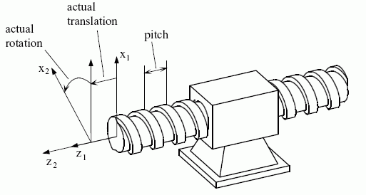
NOTE 2 The relationship between actual rotation and actual translation as drawn in the figure 13 does not actually correspond to pitch. Actual translation as drawn would result from an actual rotation covering more than a full revolution.
The motion of the second link with respect to the first link is specified by the angle required to rotate the x-axis of the first pair frame in positive direction around the common z-axis until its direction coincides with the direction of the x-axis of the second pair frame. The translation of the second link along the z-axis shall depend on the rotation according to

Hence a full rotation (actual rotation = 2π) displaces the xy-plane of the second pair frame by the value pitch in the positive z-direction relative to the first pair frame.
NOTE 3 The screw_pair does not distinguish which one of its links is driving or driven.
EXPRESS specification:
            *)

            ENTITY screw_pair

              SUBTYPE OF (low_order_kinematic_pair_with_motion_coupling);


              pitch : length_measure;
WHERE

              WR1: SIZEOF( QUERY(lr <* SELF\kinematic_pair.associated_link_representations_1 |
            NOT('KINEMATIC_STRUCTURE_SCHEMA.RIGID_LINK_REPRESENTATION' IN TYPEOF(lr)))) = 0;

            END_ENTITY;
(*
Attribute definitions:
pitch: the pitch of the screw.
Formal propositions:
WR1: All elements in the inherited attribute associated_link_representations_1 shall be of type rigid_link_representation.

EXPRESS specification:
            *)

            ENTITY screw_pair_with_range

              SUBTYPE OF (screw_pair);


              lower_limit_actual_rotation :
            OPTIONAL
            plane_angle_measure;


              upper_limit_actual_rotation :
            OPTIONAL
            plane_angle_measure;
WHERE

              WR1: (NOT EXISTS(lower_limit_actual_rotation)
            OR
            NOT EXISTS(upper_limit_actual_rotation))
            XOR
            (lower_limit_actual_rotation < upper_limit_actual_rotation);

            END_ENTITY;
(*
Attribute definitions:
lower_limit_actual_rotation: the minimum value of the pair parameter. The value of this attribute need not be specified.
upper_limit_actual_rotation: the maximum value of the pair parameter. The value of this attribute need not be specified.
Formal propositions:
WR1: The range of the screw_pair shall be positive when both bounds are not given as unlimited.

EXPRESS specification:
            *)

            ENTITY sliding_curve_pair

              SUBTYPE OF (planar_curve_pair);

            END_ENTITY;
(*

EXPRESS specification:
            *)

            ENTITY sliding_surface_pair

              SUBTYPE OF (surface_pair);

            END_ENTITY;
(*

NOTE 1 See Figure 15.
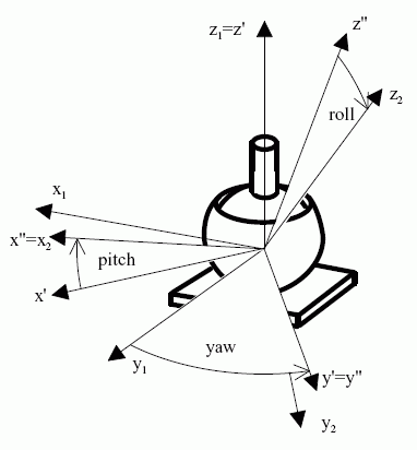
NOTE 2 (x1, y1, z1) is the frst pair frame, and (x2, y2, z2) is the second pair frame. (x', y', z') is an intermediate frame resulting from the yaw rotation of (x1, y1, z1) about z1. (x", y", z") results from the pitch rotation of (x', y', z') about y'. The roll rotation of (x", y", z") about x" produces (x2, y2, z2).
EXPRESS specification:
            *)

            ENTITY spherical_pair

              SUBTYPE OF (low_order_kinematic_pair);
DERIVE

              SELF\low_order_kinematic_pair.t_x : BOOLEAN := FALSE;

              SELF\low_order_kinematic_pair.t_y : BOOLEAN := FALSE;

              SELF\low_order_kinematic_pair.t_z : BOOLEAN := FALSE;

              SELF\low_order_kinematic_pair.r_x : BOOLEAN := TRUE;

              SELF\low_order_kinematic_pair.r_y : BOOLEAN := TRUE;

              SELF\low_order_kinematic_pair.r_z : BOOLEAN := TRUE;

            END_ENTITY;
(*
Attribute definitions:
t_x: translation along the x-axis is constraint.
t_y: translation along the y-axis is constraint.
t_z: translation along the z-axis is constraint.
r_x: rotation around the x-axis is not constraint.
r_y: rotation around the y-axis is not constraint.
r_z: rotation around the z-axis is not constraint.

EXPRESS specification:
            *)

            ENTITY spherical_pair_with_pin

              SUBTYPE OF (low_order_kinematic_pair);
DERIVE

              SELF\low_order_kinematic_pair.t_x : BOOLEAN := FALSE;

              SELF\low_order_kinematic_pair.t_y : BOOLEAN := FALSE;

              SELF\low_order_kinematic_pair.t_z : BOOLEAN := FALSE;

              SELF\low_order_kinematic_pair.r_x : BOOLEAN := FALSE;

              SELF\low_order_kinematic_pair.r_y : BOOLEAN := TRUE;

              SELF\low_order_kinematic_pair.r_z : BOOLEAN := TRUE;

            END_ENTITY;
(*
Attribute definitions:
t_x: translation along the x-axis is constraint.
t_y: translation along the y-axis is constraint.
t_z: translation along the z-axis is constraint.
r_x: rotation around the x-axis is constraint.
r_y: rotation around the y-axis is not constraint.
r_z: rotation around the z-axis is not constraint.

EXPRESS specification:
            *)

            ENTITY spherical_pair_with_pin_and_range

              SUBTYPE OF (spherical_pair_with_pin);


              lower_limit_yaw :
            OPTIONAL
            plane_angle_measure;


              upper_limit_yaw :
            OPTIONAL
            plane_angle_measure;


              lower_limit_roll :
            OPTIONAL
            plane_angle_measure;


              upper_limit_roll :
            OPTIONAL
            plane_angle_measure;
WHERE

              WR1: (NOT EXISTS(lower_limit_yaw)
            OR
            NOT EXISTS(upper_limit_yaw))
            XOR
            (lower_limit_yaw < upper_limit_yaw);

              WR2: (NOT EXISTS(lower_limit_roll)
            OR
            NOT EXISTS(upper_limit_roll))
            XOR
            (lower_limit_roll < upper_limit_roll);

            END_ENTITY;
(*
Attribute definitions:
lower_limit_yaw: the minimum value of the yaw angle for the spherical_pair. The value of this attribute need not be specified.
upper_limit_yaw: the maximum value of the yaw angle for the spherical_pair. The value of this attribute need not be specified.
lower_limit_roll: the minimum value of the roll angle for the spherical_pair. The value of this attribute need not be specified.
upper_limit_roll: the maximum value of the roll angle for the spherical_pair. The value of this attribute need not be specified.
Formal propositions:
WR1: The range of rotation about the z-axis of the spherical_pair shall be positive when both bounds are not given as unlimited.
WR2: The range of rotation about the y-axis of the spherical_pair shall be positive when both bounds are not given as unlimited.

EXPRESS specification:
            *)

            ENTITY spherical_pair_with_range

              SUBTYPE OF (spherical_pair);


              lower_limit_yaw :
            OPTIONAL
            plane_angle_measure;


              upper_limit_yaw :
            OPTIONAL
            plane_angle_measure;


              lower_limit_pitch :
            OPTIONAL
            plane_angle_measure;


              upper_limit_pitch :
            OPTIONAL
            plane_angle_measure;


              lower_limit_roll :
            OPTIONAL
            plane_angle_measure;


              upper_limit_roll :
            OPTIONAL
            plane_angle_measure;
WHERE

              WR1: (NOT EXISTS(lower_limit_yaw)
            OR
            NOT EXISTS(upper_limit_yaw))
            XOR
            (lower_limit_yaw < upper_limit_yaw);

              WR2: (NOT EXISTS(lower_limit_pitch)
            OR
            NOT EXISTS(upper_limit_pitch))
            XOR
            (lower_limit_pitch < upper_limit_pitch);

              WR3: (NOT EXISTS(lower_limit_roll)
            OR
            NOT EXISTS(upper_limit_roll))
            XOR
            (lower_limit_roll < upper_limit_roll);

            END_ENTITY;
(*
Attribute definitions:
lower_limit_yaw: the minimum value of the yaw angle for the spherical_pair. The value of this attribute need not be specified.
upper_limit_yaw: the maximum value of the yaw angle for the spherical_pair. The value of this attribute need not be specified.
lower_limit_pitch: the minimum value of the pitch angle for the spherical_pair. The value of this attribute need not be specified.
upper_limit_pitch: the maximum value of the pitch angle for the spherical_pair. The value of this attribute need not be specified.
lower_limit_roll: the minimum value of the roll angle for the spherical_pair. The value of this attribute need not be specified.
upper_limit_roll: the maximum value of the roll angle for the spherical_pair. The value of this attribute need not be specified.
Formal propositions:
WR1: The range of rotation about the z-axis of the spherical_pair shall be positive when both bounds are not given as unlimited.
WR2: The range of rotation about the y-axis of the spherical_pair shall be positive when both bounds are not given as unlimited.
WR3: The range of rotation about the x-axis of the spherical_pair shall be positive when both bounds are not given as unlimited.

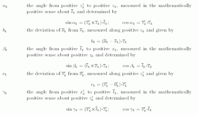
To describe the kinematic behaviour, the full shape representation of a link is not needed; rather it is sufficient to characterize the link by the transition from the link frame to all the pair frames. This shape information is captured by a set of characteristic parameters called Sheth-Uicker-Parameters, henceforth abbreviated "SU-parameters".
NOTE 1 See Figure 16. For a kinematic_link with two pairs and for the link frame coinciding with the frame of one of the pairs, this may be interpreted as the transition from the frame at the beginning of the link to the frame at the following end.
The following notation is used for frame definitions:

The following auxiliary vectors are introduced:

Then the following notation applies to SU-parameters:
ak - the (positive) distance from zkr to zk, given by

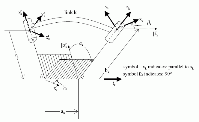
NOTE 2 For a detailed description of the Sheth-Uicker parameters see [1].
NOTE 3 In industrial robot technology the Denavit-Hartenberg parameters (DH-parameters) are widely used. See [2]. For kinematic structures with loops it is important to represent the information about the relative placement of the link axes separately from the present state of the pair. In contrast to DH-parameters, SU-parameters provide for this separation.
NOTE 4 See annex F for information on the replacement of DH-parameters by SU-parameters.
NOTE 5 An instance of su_parameters with SU-parameters as defined above is equivalent to an instance of axis2_placement_3d that has the following attribute values:

EXPRESS specification:
            *)

            ENTITY su_parameters

              SUBTYPE OF (geometric_representation_item);


              a : length_measure;


              alpha : plane_angle_measure;


              b : length_measure;


              beta : plane_angle_measure;


              c : length_measure;


              gamma : plane_angle_measure;
WHERE

              WR1: SELF\geometric_representation_item.dim=3;

            END_ENTITY;
(*
Attribute definitions:
a: specifies the SU-parameter ak.
alpha: specifies the SU-parameter αk.
b: specifies the SU-parameter bk.
beta: specifies the SU-parameter βk.
c: specifies the SU-parameter ck.
gamma: specifies the SU-parameter γk.
Formal propositions:
WR1: An su_parameters shall be used in a three dimensional geometric_representation_context.

The following notation is used:
NOTE 1 See Figure 17 for an exploded view of a surface pair. There is a rotation angle of -15° between xcp and xcq, and orientation is FALSE.
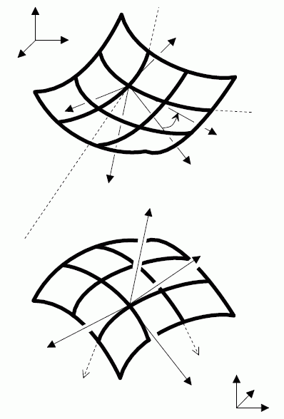
The following equations apply to sliding_surface_pair and rolling_surface_pair.
The contact frame is determined from both sides of the pair as follows, beginning with the second link:
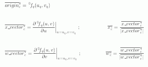


and the three direction vectors

may be used to establish the rigid homogeneous matrix representation of the placement of the contact frame qPFc relative to the second pair frame.
NOTE 2 See Figure 7 for an illustration of the relationships between the frames.
The same analysis is performed for the first link:
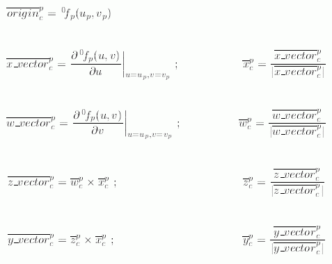
The contact point shall be identically positioned, relative to the world coordinate system, irrespective of whether it is approached from the second or the first link.

Also the z-direction at the contact point shall be identical, relative to the world coordinate system, irrespective of whether it is approached from the second or the first link.
However, the direction vectors

as evaluated above, are either

In case 1, orientation is TRUE and both z-directions are identical.
In case 2, orientation is FALSE and zcp (as well as ycp) is rotated by π about the xcp direction. Finally, xcp has to be rotated about zc until it coincides with xc.
NOTE 3 The rotation angle to achieve this is defined by the actual rotation attribute of sliding_surface_pair and of rolling_surface_pair, respectively.
EXPRESS specification:
            *)

            ENTITY surface_pair

              ABSTRACT SUPERTYPE

            OF (ONEOF (sliding_surface_pair,
                                rolling_surface_pair)
                        ANDOR surface_pair_with_range)

              SUBTYPE OF (high_order_kinematic_pair);


              surface_1 : surface;


              surface_2 : surface;


              orientation : BOOLEAN;
WHERE

              WR1: SIZEOF( QUERY(r <* SELF\kinematic_pair.associated_link_representations_1 | NOT(surface_1 IN r.items))) = 0;

              WR2: SIZEOF( QUERY(r <* SELF\kinematic_pair.associated_link_representations_2 | NOT(surface_2 IN r.items))) = 0;

              WR3: SIZEOF( QUERY(lr <* SELF\kinematic_pair.associated_link_representations_1 |
            NOT('KINEMATIC_STRUCTURE_SCHEMA.RIGID_LINK_REPRESENTATION' IN TYPEOF(lr)))) = 0;

            END_ENTITY;
(*
Attribute definitions:
surface_1: the contact surface on the first link, defined in the coordinate system.
surface_2: the contact surface on the second link, defined in the coordinate system.
orientation: an indication of whether the z-direction of the second surface agrees with the z-direction of the first surface.
Formal propositions:
WR1: The surface referenced by surface_1 shall be a member of associated_link_representations_1.
WR2: The surface referenced by surface_2 shall be a member of associated_link_representations_2.
WR3: All elements in the inherited attribute associated_link_representations_1 shall be of type rigid_link_representation.
Informal propositions:
IP1: The surfaces used as surface_1 and surface_2 shall be smooth in their entire domain, and their tangent vectors shall change their direction only in a steady manner, regardless of whether the surfaces are composed of multiple surfaces or not.
NOTE 4 This is equivalent to requiring surface_1 and surface_2 to be G1 continuous throughout and that, in the case of a rectangular_composite_surface, the transition_code shall be at least cont_same_gradient at each segment junction curve. (See ISO 10303-42.)
IP2: If the directions zq and zcp are identical, the orientation shall be set TRUE. If the directions zq and zcp are oriented in the opposite direction to each other, the orientation shall be set FALSE.

EXPRESS specification:
            *)

            ENTITY surface_pair_with_range

              SUBTYPE OF (surface_pair);


              range_on_surface_1 : rectangular_trimmed_surface;


              range_on_surface_2 : rectangular_trimmed_surface;


              lower_limit_actual_rotation :
            OPTIONAL
            plane_angle_measure;


              upper_limit_actual_rotation :
            OPTIONAL
            plane_angle_measure;
WHERE

              WR1: SELF\surface_pair.surface_1 :=: range_on_surface_1.basis_surface;

              WR2: SELF\surface_pair.surface_2 :=: range_on_surface_2.basis_surface;

              WR3: (NOT EXISTS(lower_limit_actual_rotation)
            OR
            NOT EXISTS(upper_limit_actual_rotation))
            XOR
            (lower_limit_actual_rotation < upper_limit_actual_rotation);

              WR4: SIZEOF( QUERY(r <* SELF\kinematic_pair.associated_link_representations_1 | NOT(range_on_surface_1 IN r.items))) = 0;

              WR5: SIZEOF( QUERY(r <* SELF\kinematic_pair.associated_link_representations_2 | NOT(range_on_surface_2 IN r.items))) = 0;

            END_ENTITY;
(*
Attribute definitions:
range_on_surface_1: the admissible range for the positional pair parameter value on the first contact surface.
range_on_surface_2: the admissible range for the positional pair parameter value on the second contact surface.
lower_limit_actual_rotation: the minimum value of the pair rotation parameter. The value of this attribute need not be specified.
upper_limit_actual_rotation: the maximum value of the pair rotation parameter. The value of this attribute need not be specified.
Formal propositions:
WR1: The underlying surface of range_on_surface_1 in the range specification shall be identical with the surface surface_1 in the surface_pair specification.
WR2: The underlying surface of range_on_surface_2 in the range specification shall be identical with the surface surface_2 in the surface_pair specification.
WR3: The range of rotation of the surface_pair shall be positive when both bounds are not given as unlimited.
WR4: The surface referenced by range_on_surface_1 shall be a member of associated_link_representations_1.
WR5: The surface referenced by range_on_surface_2 shall be a member of associated_link_representations_2.

NOTE 1 The unconstrained_pair may be helpful in early design stages or for kinematic analysis systems, because it allows to eliminate the constraints between two links without changing the topological structure.
NOTE 2 The concept of pair range is not applicable to an unconstrained_pair.
EXPRESS specification:
            *)

            ENTITY unconstrained_pair

              SUBTYPE OF (low_order_kinematic_pair);
DERIVE

              SELF\low_order_kinematic_pair.t_x : BOOLEAN := TRUE;

              SELF\low_order_kinematic_pair.t_y : BOOLEAN := TRUE;

              SELF\low_order_kinematic_pair.t_z : BOOLEAN := TRUE;

              SELF\low_order_kinematic_pair.r_x : BOOLEAN := TRUE;

              SELF\low_order_kinematic_pair.r_y : BOOLEAN := TRUE;

              SELF\low_order_kinematic_pair.r_z : BOOLEAN := TRUE;

            END_ENTITY;
(*
Attribute definitions:
t_x: translation along the x-axis is not constraint.
t_y: translation along the y-axis is not constraint.
t_z: translation along the z-axis is not constraint.
r_x: rotation around the x-axis is not constraint.
r_y: rotation around the y-axis is not constraint.
r_z: rotation around the z-axis is not constraint.

NOTE See Figure 18.
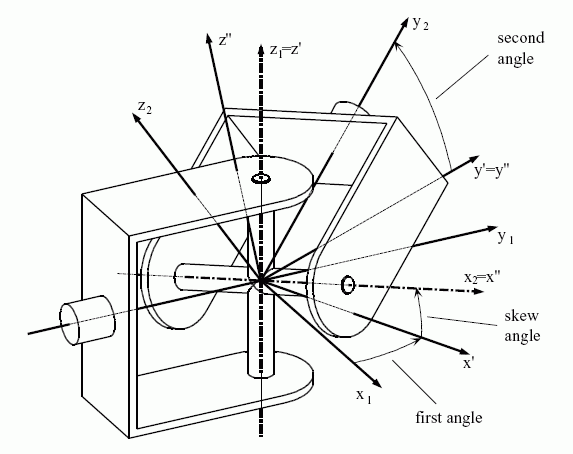
To measure those two angles of rotation, a frame system is defined on each of the links such that the origins coincide in the intersection point of the axes, the first z-axis coincides with the first axis of rotation, and the second x-axis coincides with the second axis of rotation. A third constant rotation is inserted between these two variable rotations. In order to migrate from the first pair frame to the second pair frame the following sequence of rotations has to be performed:
EXPRESS specification:
            *)

            ENTITY universal_pair

              SUBTYPE OF (low_order_kinematic_pair);


              input_skew_angle :
            OPTIONAL
            plane_angle_measure;
DERIVE

              SELF\low_order_kinematic_pair.t_x : BOOLEAN := FALSE;

              SELF\low_order_kinematic_pair.t_y : BOOLEAN := FALSE;

              SELF\low_order_kinematic_pair.t_z : BOOLEAN := FALSE;

              SELF\low_order_kinematic_pair.r_x : BOOLEAN := TRUE;

              SELF\low_order_kinematic_pair.r_y : BOOLEAN := FALSE;

              SELF\low_order_kinematic_pair.r_z : BOOLEAN := TRUE;

              skew_angle : plane_angle_measure := NVL (input_skew_angle, 0.0);
WHERE

              WR1: COS (plane_angle_for_pair_in_radian (SELF, skew_angle))
            > 0.0;

            END_ENTITY;
(*
Attribute definitions:
input_skew_angle: defines the angle by which the intersection angle between the two axes of rotation deviates from a right angle. The value of this attribute need not be specified.
t_x: translation along the x-axis is constraint.
t_y: translation along the y-axis is constraint.
t_z: translation along the z-axis is constraint.
r_x: rotation around the x-axis is not constraint.
r_y: rotation around the y-axis is constraint.
r_z: rotation around the z-axis is not constraint.
skew_angle: the angle by which the intersection angle between the two axes of rotation deviates from a right angle. If input_skew_angle is given, the value of skew_angle becomes that of input_skew_angle; otherwise it becomes zero.
Formal propositions:
WR1: The absolute value of skew_angle shall represent an acute angle.

EXPRESS specification:
            *)

            ENTITY universal_pair_with_range

              SUBTYPE OF (universal_pair);


              lower_limit_first_rotation :
            OPTIONAL
            plane_angle_measure;


              upper_limit_first_rotation :
            OPTIONAL
            plane_angle_measure;


              lower_limit_second_rotation :
            OPTIONAL
            plane_angle_measure;


              upper_limit_second_rotation :
            OPTIONAL
            plane_angle_measure;
WHERE

              WR1: (NOT EXISTS(lower_limit_first_rotation)
            OR
            NOT EXISTS(upper_limit_first_rotation))
            XOR
            (lower_limit_first_rotation < upper_limit_first_rotation);

              WR2: (NOT EXISTS(lower_limit_second_rotation)
            OR
            NOT EXISTS(upper_limit_second_rotation))
            XOR
            (lower_limit_second_rotation < upper_limit_second_rotation);

            END_ENTITY;
(*
Attribute definitions:
lower_limit_first_rotation: the minimum value of rotation around the first axis for the universal_pair. The value of this attribute need not be specified.
upper_limit_first_rotation: the maximum value of rotation around the first axis for the universal_pair. The value of this attribute need not be specified.
lower_limit_second_rotation: the minimum value of rotation around the second axis for the universal_pair. The value of this attribute need not be specified.
upper_limit_second_rotation: the maximum value of rotation around the second axis for the universal_pair. The value of this attribute need not be specified.
Formal propositions:
WR1: The range of rotation around the first axis of a universal_pair shall be positive when both bounds are not given as unlimited.
WR2: The range of rotation around the second axis of a universal_pair shall be positive when both bounds are not given as unlimited.

EXPRESS specification:
            *)
SUBTYPE_CONSTRAINT kss_representation_subtypes FOR representation;

              ONEOF (kinematic_link_representation,
         kinematic_topology_structure,
         kinematic_topology_directed_structure,
         kinematic_topology_network_structure,
         mechanism_representation,
         shape_representation);

            END_SUBTYPE_CONSTRAINT;
(*
EXPRESS specification:
         *)

         FUNCTION collect_joints (items : SET[1:?] OF pair_representation_relationship) : SET[0:?] OF kinematic_joint;
LOCAL
  result : SET OF kinematic_joint := [];
END_LOCAL;
  REPEAT i := 1 TO HIINDEX(items);
    result := result + items[i].transformation_operator.joint;
  END_REPEAT;
  RETURN(result);
         END_FUNCTION;

(*
Argument definitions:
items: the set of kinematic_joints that is the input parameter for this function.
EXPRESS specification:
         *)

         FUNCTION plane_angle_for_pair_in_radian (pair : kinematic_pair; angle : plane_angle_measure) : plane_angle_measure;
LOCAL
    converted_angle : plane_angle_measure := angle;
    link_rep        : kinematic_link_representation
                    := representation_of_link (pair.joint.edge_start);
    link_cntxt      : representation_context;
    pa_units        : SET OF unit := [];
    pau             : unit;
  END_LOCAL;

  link_cntxt := link_rep\representation.context_of_items;

  IF NOT ('MEASURE_SCHEMA.GLOBAL_UNIT_ASSIGNED_CONTEXT'
          IN TYPEOF (link_cntxt)) THEN
    RETURN (?);
  END_IF;

  pa_units := QUERY (unit <* link_cntxt\global_unit_assigned_context.units |
                     'MEASURE_SCHEMA.PLANE_ANGLE_UNIT' IN TYPEOF (unit));

  IF SIZEOF (pa_units) <> 1 THEN
    RETURN (?);
  END_IF;

  pau := pa_units[1];

  IF (NOT ('MEASURE_SCHEMA.SI_UNIT' IN TYPEOF (pau)) AND
      NOT ('MEASURE_SCHEMA.CONVERSION_BASED_UNIT' IN TYPEOF (pau))) THEN
    RETURN (?);
  END_IF;

  REPEAT WHILE ('MEASURE_SCHEMA.CONVERSION_BASED_UNIT' IN TYPEOF (pau));
    converted_angle := converted_angle *
                       pau\conversion_based_unit.conversion_factor.
                       value_component;
    pau := pau\conversion_based_unit.conversion_factor.unit_component;

    IF ((NOT ('MEASURE_SCHEMA.SI_UNIT' IN TYPEOF (pau)) AND
         NOT ('MEASURE_SCHEMA.CONVERSION_BASED_UNIT' IN TYPEOF (pau))) OR
        (NOT ('MEASURE_SCHEMA.PLANE_ANGLE_UNIT' IN TYPEOF (pau)))) THEN
      RETURN (?);
    END_IF;
  END_REPEAT;

  IF (pau\si_unit.name <> si_unit_name.radian) THEN
    RETURN (?);
  END_IF;

  CASE pau\si_unit.prefix OF
    si_prefix.exa     : RETURN (1.E18 * converted_angle);
    si_prefix.peta    : RETURN (1.E15 * converted_angle);
    si_prefix.tera    : RETURN (1.E12 * converted_angle);
    si_prefix.giga    : RETURN (1.E9 * converted_angle);
    si_prefix.mega    : RETURN (1.E6 * converted_angle);
    si_prefix.kilo    : RETURN (1.E3 * converted_angle);
    si_prefix.hecto   : RETURN (1.E2 * converted_angle);
    si_prefix.deca    : RETURN (1.E1 * converted_angle);
    si_prefix.deci    : RETURN (1.E-1 * converted_angle);
    si_prefix.centi   : RETURN (1.E-2 * converted_angle);
    si_prefix.milli   : RETURN (1.E-3 * converted_angle);
    si_prefix.micro   : RETURN (1.E-6 * converted_angle);
    si_prefix.nano    : RETURN (1.E-9 * converted_angle);
    si_prefix.pico    : RETURN (1.E-12 * converted_angle);
    si_prefix.femto   : RETURN (1.E-15 * converted_angle);
    si_prefix.atto    : RETURN (1.E-18 * converted_angle);
  OTHERWISE           : RETURN (converted_angle);
  END_CASE;
         END_FUNCTION;

(*
Argument definitions:
pair: the kinematic_pair the context of whose is to be evaluated for the conversion factor.
angle: the angle that is converted to an angle in radians.
EXPRESS specification:
         *)

         FUNCTION representation_of_link (link : kinematic_link) : kinematic_link_representation;
RETURN (?);
         END_FUNCTION;

(*
Argument definitions:
link: the kinematic_link for which the related kinematic_link_representation is wanted.
EXPRESS specification:
         *)

         FUNCTION sort_link_associations (aprr : SET[1:?] OF pair_representation_relationship; one_not_two : BOOLEAN) : SET[0:?] OF kinematic_link_representation;
LOCAL
  result : SET OF kinematic_link_representation := [];
END_LOCAL;
  IF one_not_two THEN
    REPEAT i := 1 TO HIINDEX(aprr);
      result := result + aprr[i].rep_1;
    END_REPEAT;
  ELSE
    REPEAT i := 1 TO HIINDEX(aprr);
      result := result + aprr[i].rep_2;
    END_REPEAT;
  END_IF;
  RETURN(result);
         END_FUNCTION;

(*
Argument definitions:
aprr: the set of pair_representation_relationships that is being investigated.
one_not_two: specifies on whether the rep_1 or the rep_2 attribute of a pair_representation_relationship shall be extracted.
         *)

         END_SCHEMA;  -- kinematic_structure_schema
(*
© ISO 2019 — All rights reserved