| Integrated application resource: Kinematics | ISO 10303-105:2019(E) © ISO |
The subject of the kinematic_topology_schema is the description of the topology of a kinematic structure consisting of kinematic joints and links, independent of particular pair types, ranges and geometry.
This clause defines the information requirements to which implementations shall conform using the EXPRESS language as defined in ISO 10303-11. The following EXPRESS declaration begins the kinematic_topology_schema and identifies the necessary external references.Short names of entities defined in this schema are described in Annex A. Unambiguous identification of this schema is defined in Annex B.
EXPRESS specification:
         *)

            	SCHEMA kinematic_topology_schema;
            REFERENCE FROM
            representation_schema

               --
            ISO 10303-43
  (representation);
            REFERENCE FROM
            topology_schema

               --
            ISO 10303-42
  (connected_edge_set,


            edge,


            edge_loop,


            oriented_edge,


            path,


            vertex);

(*
NOTE 1 The schemas referenced above are specified in the following parts:
representation_schema ISO 10303-43 topology_schema ISO 10303-42
NOTE 2 See Annex D for a graphical representation of this schema.
Kinematic topology is a specialization of general topological concepts defined in the topology_schema of ISO 10303-42.
The kinematic_topology_schema provides different kinds of representations for the purpose of representing kinematic topology:
A kinematic_topology_structure provides the basic grouping of connected kinematic topology elements, where the edges are given by kinematic_joints that references two kinematic_links as their vertices. All the other kinematic representations use a kinematic_topology_structure as their parent, of which a connected sub-set of the kinematic_joints is referenced and that are sharing the same representation_context.
A kinematic_topology_substructure is used to represent a sub-set of kinematic_joints of the parent kinematic_topology_structure or another kinematic_topology_substructure.
A kinematic_topology_directed_structure defines a directed graph within a kinematic_topology_structure by using oriented_joints. When using the subtype kinematic_topology_tree_structure the directed graph is required to be acyclic.

EXPRESS specification:
            *)

            TYPE
            kinematic_topology_representation_select
            =


            SELECT

               (kinematic_topology_structure,
    kinematic_topology_directed_structure,
    kinematic_topology_network_structure);

            END_TYPE;

            (*

A topological orientation is always implicitly associated with a joint. This orientation is defined as being from the edge start to the edge end.
For a kinematic_pair referencing a kinematic_joint, the transform_item_1 shall be an item of the kinematic_link_representation of the edge_start of the kinematic_joint.
Similarly, the transform_item_2 shall be an item of the kinematic_link_representation of the edge_end of the kinematic_joint.
NOTE 1 The type of constraint on the relative motion is defined by the kinematic_pair that has the joint as its joint attribute. In a graph representation of the topology, the kinematic_joint represents an oriented edge connecting two vertices in the graph. The orientation of the kinematic_joint reflects an implicit orientation which is arbitrary, except for the rack-and-pinion pair, the point-on-surface pair, and the point-on-planar-curve pair.
NOTE 2 If the sequence of edge_start and edge_end is interchanged, both, pair values and pair range values, have to be used with the opposite signs additionally the attributes giving a lower limit are to be interchanged with those giving the corresponding upper limit.
EXPRESS specification:
            *)

            ENTITY kinematic_joint

              SUBTYPE OF (edge);


              SELF\edge.edge_start : kinematic_link;


              SELF\edge.edge_end : kinematic_link;
UNIQUE

              UR1: edge_start, edge_end;
WHERE

              WR1: edge_start :<>: edge_end;

            END_ENTITY;
(*
Attribute definitions:
edge_start: the link through which the joint is entered.
edge_end: the link through which the joint is left.
Formal propositions:
UR1: The combination of edge_start and edge_end shall be unique within a population of kinematic_joint.
WR1: The edge_start and edge_end shall not be identical.

EXPRESS specification:
            *)

            ENTITY kinematic_link

              SUBTYPE OF (vertex);

            END_ENTITY;
(*

Every kinematic_joint shall be oriented such that the list of kinematic_joints have a common orientation within the loop.
NOTE This entity is present in an instance of a kinematics model only if the kinematic structure takes the form of a directed graph.
EXPRESS specification:
            *)

            ENTITY kinematic_loop

              SUBTYPE OF (edge_loop);


              SELF\path.edge_list : LIST[1:?] OF
            UNIQUE
            oriented_joint;

            END_ENTITY;
(*
Attribute definitions:
edge_list: an inherited attribute that shall be of type oriented_joint There shall exist at least one oriented_joint for the kinematic_loop.

EXPRESS specification:
            *)

            ENTITY kinematic_topology_directed_structure

              SUBTYPE OF (representation);


              SELF\representation.items : SET[1:?] OF oriented_joint;


              parent : kinematic_topology_structure;
WHERE

              WR1: context_of_items :=: parent.context_of_items;

              WR2: get_kinematic_joints_from_oriented_joints(items) <= parent.items;

            END_ENTITY;
(*
Attribute definitions:
items: an inherited attribute that shall be of type oriented_joint. There shall exist at least one oriented_joint for the kinematic_topology_directed_structure.
parent: the parent kinematic_topology_structure in which this kinematic_topology_directed_structure defines a direct subset.
Formal propositions:
WR1: A kinematic_topology_directed_structure shall have the same context as its parent.
WR2: The oriented_joints used by the items of a kinematic_topology_directed_structure shall also be items of its parent.

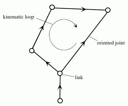
NOTE 1 See Figure 2 for an illustration of a kinematic network structure.
NOTE 2 This entity is present in an instance of a kinematics model only if the kinematic structure takes the form of a directed graph.

EXPRESS specification:
            *)

            ENTITY kinematic_topology_network_structure

              SUBTYPE OF (representation);


              SELF\representation.items : SET[1:?] OF kinematic_loop;


              parent : kinematic_topology_structure;
WHERE

              WR1: context_of_items :=: parent.context_of_items;

              WR2: get_kinematic_joints_from_kinematic_loops(items) <= parent.items;

            END_ENTITY;
(*
Attribute definitions:
items: an inherited attribute that shall be of type kinematic_loop. There shall exist at least one kinematic_loop for the kinematic_topology_network_structure.
parent: the parent kinematic_topology_structure in which this kinematic_topology_network_structure defines a subset with loops.
Formal propositions:
WR1: A kinematic_topology_network_structure shall have the same context as the parent.
WR2: The oriented_joints used by the items of a kinematic_topology_network_structure shall also be items of its parent.

NOTE Every kinematic structure can be described in terms of its joints and links. Joints constrain the motion between two rigid objects called links. Joints and links are sufficient to describe the topology of kinematic structures, but for computation it is meaningful to introduce additional levels of structure based on graph theory. Information related to the graph representation of a kinematic structure is given in kinematic_topology_substructure.
EXPRESS specification:
            *)

            ENTITY kinematic_topology_structure

              SUBTYPE OF (representation);


              SELF\representation.items : SET[1:?] OF kinematic_joint;
WHERE

              WR1: SIZEOF (QUERY (item <* items | 'TOPOLOGY_SCHEMA.ORIENTED_EDGE' in TYPEOF(item))) = 0;

            END_ENTITY;
(*
Attribute definitions:
items: the set of kinematic_joints that compose the kinematic_topology_structure of a mechanism. There shall exist one or more kinematic_joints for the kinematic_topology_structure.
Formal propositions:
WR1: None of the items shall be an oriented_edge.

NOTE 1 Using graph theory, the topology of a mechanism is represented by a directed graph, where the links correspond to the nodes, and the joints correspond to the edges. This graph can be derived from the definition of the links and joints. If the topology of a mechanism is defined only by this minimal information, it is referred to as "lower level topology" within this part of ISO 10303.
Graph theory provides a means to capture connectivity information which may be applied to the describe the topological structure of mechanisms. The geometrical and mechanical properties are not conveyed. If the full topological information including connectivity information is provided explicitly, this is referred to as "higher level topology" within this part of ISO 10303.
A general graph may be composed of two basic types of subgraphs:
If, in addition to the lower level of topology, the higher level topology is provided in a kinematic model, this higher level of topology is represented by kinematic substructures. These kinematic substructures are:
NOTE 2 See [4] for methods that can be applied to analyze a kinematic topology substructure.
EXPRESS specification:
            *)

            ENTITY kinematic_topology_substructure

              SUBTYPE OF (kinematic_topology_structure);


              parent : kinematic_topology_structure;
WHERE

              WR1: context_of_items :=: parent.context_of_items;

              WR2: SELF\kinematic_topology_structure.items <= parent\kinematic_topology_structure.items;

            END_ENTITY;
(*
Attribute definitions:
parent: the kinematic_topology_structure of which the kinematic_topology_substructure forms a component.
Formal propositions:
WR1: A kinematic_topology_substructure shall have the same context as the parent.
WR2: The items of a kinematic_topology_substructure shall also be items of the parent.

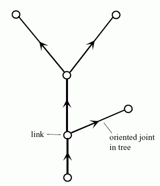
NOTE 1 See Figure 3 for an illustration of a kinematic topology tree structure.
NOTE 2 This entity is present in an instance of a kinematics model only if the kinematic topology structure takes the form of a directed graph.

EXPRESS specification:
            *)

            ENTITY kinematic_topology_tree_structure

              SUBTYPE OF (kinematic_topology_directed_structure);

            END_ENTITY;
(*

NOTE This entity is present in an instance of a kinematics model only if the kinematic structure takes the form of a directed graph.
EXPRESS specification:
            *)

            ENTITY oriented_joint

              SUBTYPE OF (oriented_edge);


              SELF\oriented_edge.edge_element : kinematic_joint;

            END_ENTITY;
(*
Attribute definitions:
edge_element: an inherited attribute that shall be of type kinematic_joint.

The kts_representation_subtypes constraint specifies a constraint that applies to instances of subtypes of representation.
A kts_representation_subtypes is a constraint that specifies the subtypes kinematic_topology_structure, kinematic_topology_directed_structure and kinematic_topology_network_structure of representation are mutually exclusive.EXPRESS specification:
            *)
SUBTYPE_CONSTRAINT kts_representation_subtypes FOR representation;

              ONEOF (kinematic_topology_structure,
         kinematic_topology_directed_structure,
         kinematic_topology_network_structure);

            END_SUBTYPE_CONSTRAINT;
(*
EXPRESS specification:
         *)

         FUNCTION get_kinematic_joints_from_kinematic_loops (kls : SET[0:?] OF kinematic_loop) : SET[0:?] OF kinematic_joint;
LOCAL
    result : SET OF oriented_joint := [];
  END_LOCAL;
  IF SIZEOF(kls) > 0 THEN
    REPEAT i := 1 TO HIINDEX(kls);
      result := result + kls[i].edge_list;
    END_REPEAT;
  END_IF;
  RETURN (get_kinematic_joints_from_oriented_joints(result));
         END_FUNCTION;

(*
Argument definitions:
kls: the specified set of kinematic_loops.
EXPRESS specification:
         *)

         FUNCTION get_kinematic_joints_from_oriented_joints (ors : SET[0:?] OF oriented_joint) : SET[0:?] OF kinematic_joint;
LOCAL
    result : SET OF kinematic_joint := [];
  END_LOCAL;
  IF SIZEOF(ors) > 0 THEN
    REPEAT i := 1 TO HIINDEX(ors);
      result := result + ors[i].edge_element;
    END_REPEAT;
  END_IF;
  RETURN (result);
         END_FUNCTION;

(*
Argument definitions:
ors: the specified set of oriented_joints.
         *)

         END_SCHEMA;  -- kinematic_topology_schema
(*
© ISO 2019 — All rights reserved