|
|
Application module:
Mechanical design features and requirements |
ISO/TS 10303-1846:2021(E)
© ISO
|
This clause specifies the information requirements for the
Mechanical design features and requirements
application module. The information requirements are specified as the
Application Reference Model (ARM) of this application module.
NOTE 1 A graphical representation of the information
requirements is given in
Annex C.
NOTE 2 The mapping specification is specified in
5.1. It shows how
the information requirements are met by using common resources and
constructs defined or imported in the MIM schema of this application
module.
This clause defines the information requirements to which implementations shall
conform using the EXPRESS language as defined in ISO 10303-11.
The following begins the
Mechanical_design_features_and_requirements_arm
schema and identifies the necessary external references.
EXPRESS specification:
         *)

            SCHEMA Mechanical_design_features_and_requirements_arm;
(*
The following EXPRESS interface statements specify the elements
imported from the ARMs of other application modules.
EXPRESS specification:
*)

            USE FROM
            Assembly_structure_arm;
               --
            ISO/TS 10303-1026
            USE FROM
            Associative_draughting_elements_arm;
               --
            ISO/TS 10303-1311
            USE FROM
            Characterizable_object_arm;
               --
            ISO/TS 10303-1765
            USE FROM
            Dimension_tolerance_arm;
               --
            ISO/TS 10303-1050
            USE FROM
            Elemental_geometric_shape_arm;
               --
            ISO/TS 10303-1004
            USE FROM
            Geometric_tolerance_arm;
               --
            ISO/TS 10303-1051
            USE FROM
            Machining_features_arm;
               --
            ISO/TS 10303-1814
            USE FROM
            Part_view_definition_arm;
               --
            ISO/TS 10303-1023
            USE FROM
            Requirement_assignment_arm;
               --
            ISO/TS 10303-1233
            USE FROM
            Shape_property_assignment_arm;
               --
            ISO/TS 10303-1032
            USE FROM
            Value_with_unit_extension_arm;
               --
            ISO/TS 10303-1753
(*
NOTE 1
The schemas referenced above are specified in the following
part of ISO 10303:
| Assembly_structure_arm |
ISO/TS 10303-1026 |
| Associative_draughting_elements_arm |
ISO/TS 10303-1311 |
| Characterizable_object_arm |
ISO/TS 10303-1765 |
| Dimension_tolerance_arm |
ISO/TS 10303-1050 |
| Elemental_geometric_shape_arm |
ISO/TS 10303-1004 |
| Geometric_tolerance_arm |
ISO/TS 10303-1051 |
| Machining_features_arm |
ISO/TS 10303-1814 |
| Part_view_definition_arm |
ISO/TS 10303-1023 |
| Requirement_assignment_arm |
ISO/TS 10303-1233 |
| Shape_property_assignment_arm |
ISO/TS 10303-1032 |
| Value_with_unit_extension_arm |
ISO/TS 10303-1753 |
NOTE 2
See Annex C,
Figures
C.1, C.2, C.3, C.4, C.5, C.6and C.7
for a graphical representation of this schema.
This subclause specifies the ARM types
for this application module. The ARM types and
definitions are specified below.
The md_requirement_assignment_item type is an extension
of the
requirement_assignment_item type.
It adds the data
types
Characterizable_object, Geometric_dimension, Geometric_tolerance, Product, Product_version, Product_view_definition, Shape_element, and View_definition_relationship
to the list of alternate data types.
EXPRESS specification:
            *)

            TYPE
            md_requirement_assignment_item =


            SELECT
            BASED_ON
            requirement_assignment_item
            WITH


               (Characterizable_object,
    Geometric_dimension,
    Geometric_tolerance,
    Product,
    Product_version,
    Product_view_definition,
    Shape_element,
    View_definition_relationship);

            END_TYPE;

            (*
The md_requirement_source_item type is an extension
of the
requirement_source_item type.
It adds the data
types
Characterizable_object, Geometric_dimension, Geometric_tolerance, Product, Product_version, Product_view_definition, Shape_element, and View_definition_relationship
to the list of alternate data types.
EXPRESS specification:
            *)

            TYPE
            md_requirement_source_item =


            SELECT
            BASED_ON
            requirement_source_item
            WITH


               (Characterizable_object,
    Geometric_dimension,
    Geometric_tolerance,
    Product,
    Product_version,
    Product_view_definition,
    Shape_element,
    View_definition_relationship);

            END_TYPE;

            (*
The md_tolerance_value_or_limits_and_fits type allows for the designation of the data
types
Length_plus_minus_bounds and Limits_and_fits.
EXPRESS specification:
            *)

            TYPE
            md_tolerance_value_or_limits_and_fits =


            SELECT

               (Length_plus_minus_bounds,
    Limits_and_fits);

            END_TYPE;

            (*
This subclause specifies the ARM entities for this
module. Each ARM application entity is an atomic element that
embodies a unique application concept and contains attributes
specifying the data elements of the entity. The ARM
entities and definitions are specified below.
A Basic_round_hole is a type of
Hole
that defines a template structure that provides the parametric requirements for a hole in a design context.
EXPRESS specification:
            *)

            ENTITY Basic_round_hole

              SUBTYPE OF (Hole);


              depth :
            OPTIONAL
            Positive_length_data_element;


              depth_tolerance :
            OPTIONAL
            Length_plus_minus_bounds;


              diameter : Positive_length_data_element;


              diameter_tolerance :
            OPTIONAL
            md_tolerance_value_or_limits_and_fits;


              through_hole : BOOLEAN;


              SELF\Characterizable_object.primary_shape_representation RENAMED placement_model : Geometric_model;
DERIVE

              SELF\Machining_feature.placement : Axis_placement_3d := get_the_placement(placement_model);
WHERE

              WR1: SIZEOF(QUERY(ri                <* placement_model\Geometric_model.items                | ('ELEMENTAL_GEOMETRIC_SHAPE_ARM.AXIS_PLACEMENT_3D'
            IN TYPEOF(ri)))) =   1;

              WR2: SIZEOF(['MACHINING_FEATURES_ARM.COUNTERBORE_HOLE',           'MACHINING_FEATURES_ARM.COUNTERSUNK_HOLE',           'MACHINING_FEATURES_ARM.ROUND_HOLE',
            'MECHANICAL_DESIGN_FEATURES_AND_REQUIREMENTS_ARM.EXPLICIT_COMPOSITE_HOLE'] *          TYPEOF(SELF)) =   0;

              WR3: NOT EXISTS(SELF\Multi_axis_feature.maximum_feature_limit);

              WR4: NOT EXISTS(SELF\Characterizable_object.auxiliary_shape_representations);

              WR5: NOT EXISTS(SELF\Characterizable_object.shape_type);

              WR6: NOT EXISTS(SELF\Characterizable_object.description);

              WR7: through_hole XOR EXISTS(depth);

            END_ENTITY;
(*
Attribute definitions:
depth:
specifies the depth of the drilled hole. The value of this attribute need not be specified.
depth_tolerance:
specifies the tolerance of the depth. The value of this attribute need not be specified.
diameter:
specifies the diameter of the drilled hole.
diameter_tolerance:
specifies the tolerance of the hole diameter. The value of this attribute need not be specified.
through_hole:
specifies that the drilled hole is required to be completely through the item being drilled.
placement_model:
specifies a Geometric_model
that contains as a minimum an Axis_placement_3d
that is the placement origin for orientation and position.
placement:
specifies a derived attribute that is also a redeclaration of the placement that specifies the placement axis of the hole.
The axis is the only Axis_placement_3d in the placement_model; therefore, it is calculated rather than being explicitly provided.
Formal propositions:
WR1:
One member of placement_model shall be an Axis_placement_3d.
WR2:
An Basic_round_hole shall not be a Counterbore_hole, Countersunk_hole, Round_hole or an Explicit_round_hole.
WR3:
The maximum_feature_limit shall not be populated.
WR4:
The auxiliary_shape_representations shall not be populated.
WR5:
The shape_type shall not be populated.
WR6:
The description shall not be populated.
WR7:
The member of Basic_round_hole provided shall specify that the hole is drilled completely through the itemor it shall specify a depth; however, the member
of Basic_round_hole provided shall not specify that the hole isdrilled completely through the item and specify a depth.
A Basic_round_hole_occurrence is a type of
Shape_element that is an application of the definition in the design context.
EXPRESS specification:
            *)

            ENTITY Basic_round_hole_occurrence

              SUBTYPE OF (Shape_element);


              definition : Basic_round_hole;
WHERE

              WR1: 'PART_VIEW_DEFINITION_ARM.PART_VIEW_DEFINITION' IN TYPEOF(SELF\Shape_element.associated_definition);

              WR2: SELF\Shape_element.product_definitional = TRUE;

            END_ENTITY;
(*
Attribute definitions:
definition:
specifies the Basic_round_hole that provides the parametric data values and geometric reference data values of the Basic_round_hole_occurrence.
Formal propositions:
WR1:
the Basic_round_hole_occurrence shall be associated with a definition of a product.
WR2:
the placement of the hole shall be on the surface of the item.
A Basic_round_hole_occurrence_in_assembly is a type of Basic_round_hole_occurrence that is associated with a product definition that is an assembly.
EXPRESS specification:
            *)

            ENTITY Basic_round_hole_occurrence_in_assembly

              SUBTYPE OF (Basic_round_hole_occurrence);


              modified_components : LIST[1:?] OF
            UNIQUE
            Multi_level_reference_designator;

            END_ENTITY;
(*
Attribute definitions:
modified_components:
specifies the components the hole penetrates.
An Explicit_round_hole is a type of
Hole
that includes the data elements locally rather than in a separate representation as specified in the
Hole
supertype.
EXPRESS specification:
            *)

            ENTITY Explicit_round_hole

              SUBTYPE OF (Hole);


              depth : Positive_length_data_element;


              depth_tolerance :
            OPTIONAL
            Length_plus_minus_bounds;


              diameter : Positive_length_data_element;


              diameter_tolerance :
            OPTIONAL
            md_tolerance_value_or_limits_and_fits;


              SELF\Characterizable_object.primary_shape_representation RENAMED placement_model : Geometric_model;
DERIVE

              SELF\Machining_feature.placement : Axis_placement_3d := get_the_placement(placement_model);
WHERE

              WR1: SIZEOF(QUERY(ri                <* placement_model\Geometric_model.items                | ('ELEMENTAL_GEOMETRIC_SHAPE_ARM.AXIS_PLACEMENT_3D'
            IN TYPEOF(ri)))) =   1;

              WR2: SIZEOF(['MACHINING_FEATURES_ARM.COUNTERBORE_HOLE',           'MACHINING_FEATURES_ARM.COUNTERSUNK_HOLE',           'MACHINING_FEATURES_ARM.ROUND_HOLE',
            'MECHANICAL_DESIGN_FEATURES_AND_REQUIREMENTS_ARM.EXPLICIT_COMPOSITE_HOLE'] *          TYPEOF(SELF)) =   0;

              WR3: NOT EXISTS(SELF\Multi_axis_feature.maximum_feature_limit);

              WR4: NOT EXISTS(SELF\Characterizable_object.auxiliary_shape_representations);

              WR5: NOT EXISTS(SELF\Characterizable_object.shape_type);

              WR6: NOT EXISTS(SELF\Characterizable_object.description);

            END_ENTITY;
(*
Attribute definitions:
depth:
specifies the required hole depth.
depth_tolerance:
specifies the tolerance of the depth. The value of this attribute need not be supplied.
diameter:
specifies the hole diameter.
diameter_tolerance:
specifies the tolerance of the hole diameter. The value of this attribute need not be supplied.
placement_model:
specifies a Geometric_model that contains an
Axis_placement_3d
that is the placement origin for orientation and position.
placement:
specifies a derived attribute that is also a redeclaration of the
placement
that specifies the placement axis of the hole. The axis is the only element in the placement_model;
therefore, it is calculated rather than being explicitly provided.
Formal propositions:
WR1:
one item in the placement_model shall be an
Axis_placement_3d.
WR2:
An Explicit_round_hole shall not be Counterbore_hole, Countersunk_hole, Round_hole or Explicit_composite_hole.
WR3:
The
maximum_feature_limit
shall not be populated.
WR4:
The
auxiliary_shape_representations
shall not be populated.
WR5:
The
shape_type
shall not be populated.
WR6:
The
description
shall not be populated.
An Explicit_composite_hole is a type of
Hole
that includes the data elements locally rather than in a separate representation as specified in the
Hole
supertype.
EXPRESS specification:
            *)

            ENTITY Explicit_composite_hole

              SUBTYPE OF (Hole);


              SELF\Characterizable_object.primary_shape_representation RENAMED placement_model : Geometric_model;
DERIVE

              SELF\Machining_feature.placement : Axis_placement_3d := get_the_placement(placement_model);
WHERE

              WR1: SIZEOF(QUERY(ri                <* placement_model\Geometric_model.items                | ('ELEMENTAL_GEOMETRIC_SHAPE_ARM.AXIS_PLACEMENT_3D'
            IN TYPEOF(ri)))) =   1;

              WR2: SIZEOF(['MACHINING_FEATURES_ARM.COUNTERBORE_HOLE',           'MACHINING_FEATURES_ARM.COUNTERSUNK_HOLE',           'MACHINING_FEATURES_ARM.ROUND_HOLE',
            'MECHANICAL_DESIGN_FEATURES_AND_REQUIREMENTS_ARM.EXPLICIT_ROUND_HOLE'] *          TYPEOF(SELF)) =   0;

              WR3: NOT EXISTS(SELF\Multi_axis_feature.maximum_feature_limit);

              WR4: NOT EXISTS(SELF\Characterizable_object.auxiliary_shape_representations);

              WR5: NOT EXISTS(SELF\Characterizable_object.shape_type);

              WR6: NOT EXISTS(SELF\Characterizable_object.description);

            END_ENTITY;
(*
Attribute definitions:
placement_model:
specifies a Geometric_model
that contains as a minimum an
Axis_placement_3d
that is the placement origin for orientation and position.
placement:
specifies a derived attribute that is also a redeclaration of the
placement
that specifies the placement axis of the hole. The axis is the only
Axis_placement_3d
in the placement_model; therefore, it is calculated rather than being explicitly provided.
Formal propositions:
WR1:
One member of placement_model shall be an
Axis_placement_3d.
WR2:
An Explicit_round_hole shall not be a Counterbore_hole, Countersunk_hole, Round_hole or an Explicit_round_hole.
WR3:
The
maximum_feature_limit
shall not be populated.
WR4:
The
auxiliary_shape_representations
shall not be populated.
WR5:
The
shape_type
shall not be populated.
WR6:
The
description
shall not be populated.
Informal propositions:
IP1:
The
Axis_placement_3d
in the placement shall define the reference position and orientation for the
Md_counterbore_hole_definition
.
IP2:
The z-axis of the
Axis_placement_3d
shall point into the material of the item being bored.
IP3:
The placement of the
Axis_placement_3d
shall be on the surface of the item being bored.
IP4:
The drill axis and each bore axis shall be congruent with the z-axis of the placement.
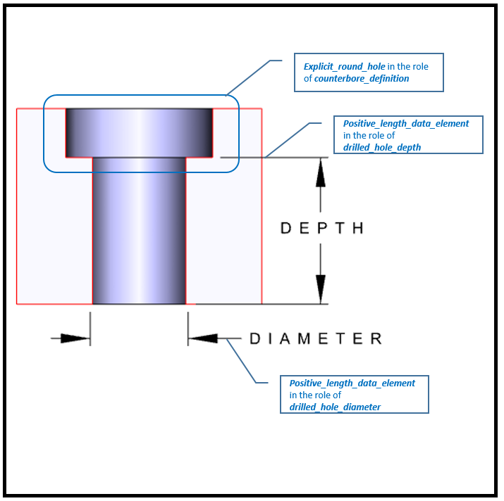
An Md_counterbore_hole_definition is a type of
Characterizable_object
that defines a template structure that provides the parametric requirements for a counterbore hole in a design context.
The template includes one or more ordered
to provide a sequence of bores and a drilled hole.
NOTE 1
When applicable see ASME Y14.5-2009[2].
NOTE 2
See Figure 1 for an illustration of the attributes.
Figure 1 — Single bore option attributes for an Md_counterbore_hole_definition
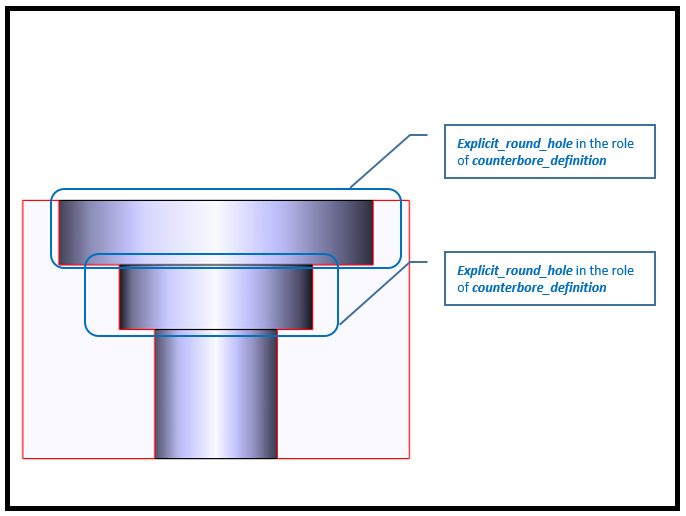
NOTE 3
See Figure 2 for an illustration of the attributes of a counterbore hole with multiple bores.
Figure 2 — Multiple bore option attributes for an Md_counterbore_hole_definition
EXPRESS specification:
            *)

            ENTITY Md_counterbore_hole_definition

              SUBTYPE OF (Explicit_composite_hole);


              counterbore_definition : LIST[1:?] OF
            UNIQUE
            Explicit_round_hole;


              drilled_hole_depth :
            OPTIONAL
            Positive_length_data_element;


              drilled_hole_depth_tolerance :
            OPTIONAL
            Length_plus_minus_bounds;


              drilled_hole_diameter : Positive_length_data_element;


              drilled_hole_diameter_tolerance :
            OPTIONAL
            md_tolerance_value_or_limits_and_fits;


              through_hole : BOOLEAN;


              shape_model : Geometric_model;
WHERE

              WR1: through_hole XOR EXISTS(drilled_hole_depth);

            END_ENTITY;
(*
Attribute definitions:
counterbore_definition:
specifies the list of bores that make up the compound counterbore hole by ascending order.
drilled_hole_depth:
specifies the depth of the drilled hole.
drilled_hole_depth_tolerance:
specifies the tolerance of the drilled_hole_depth. The value of this attribute need not be supplied.
drilled_hole_diameter:
specifies the diameter of the drilled hole.
drilled_hole_diameter_tolerance:
specifies the tolerance of the drilled_hole_diameter. The value of this attribute need not be supplied.
through_hole:
specifies that the drilled hole is required to be completely through the item being drilled.
shape_model:
a shape_model that contains as a minimum an
Axis_placement_3d
that is a placement origin for orientation and position.
Formal propositions:
WR1:
The member of Md_counterbore_hole_definition provided shall specify that the hole is drilled completely through the item
or it shall specify a depth; however, the member of Md_counterbore_hole_definition provided shall not specify that the hole is
drilled completely through the item and specify a depth.
A Simplified_md_counterbore_hole_definition is a type of
Md_counterbore_hole_definition
that provides the minimal or no geometric definition for the hole.
EXPRESS specification:
            *)

            ENTITY Simplified_md_counterbore_hole_definition

              SUBTYPE OF (Md_counterbore_hole_definition);


              SELF\Md_counterbore_hole_definition.shape_model RENAMED position : Geometric_model;
WHERE

              WR1: SIZEOF(position\Geometric_model.items) = 1;

            END_ENTITY;
(*
Attribute definitions:
position:
specifies a shape_model that includes the placement origin for the hole definition.
Formal propositions:
WR1:
There shall be exactly one item in the shape_model specified by position.
An Md_counterbore_hole_occurrence is a type of
Shape_element
that is an application of the definition in the design context.
EXPRESS specification:
            *)

            ENTITY Md_counterbore_hole_occurrence

              SUBTYPE OF (Shape_element);


              definition : Md_counterbore_hole_definition;
WHERE

              WR1: 'PART_VIEW_DEFINITION_ARM.PART_VIEW_DEFINITION' IN TYPEOF(SELF\Shape_element.associated_definition);

              WR2: SELF\Shape_element.product_definitional = TRUE;

            END_ENTITY;
(*
Attribute definitions:
definition:
specifies the
Md_counterbore_hole_definition
that provides the parametric data values and geometric reference data values of the
Md_counterbore_hole_occurrence.
Formal propositions:
WR1:
the Md_counterbore_hole_occurence shall be associated with a definition of a product.
WR2:
the placement of the hole shall be on the surface of the item.
An Md_counterbore_hole_occurrence_in_assembly is a type of
Md_counterbore_hole_occurrence
that is associated with a product definition that is an assembly.
EXPRESS specification:
            *)

            ENTITY Md_counterbore_hole_occurrence_in_assembly

              SUBTYPE OF (Md_counterbore_hole_occurrence);


              modified_components : LIST[1:?] OF
            UNIQUE
            Multi_level_reference_designator;

            END_ENTITY;
(*
Attribute definitions:
modified_components:
specifies the components the hole penetrates.
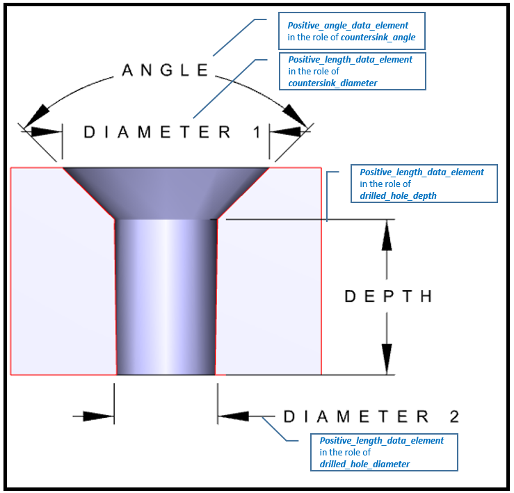
An Md_countersink_hole_definition is a type of
Characterizable_object
that defines a template to structure the requirements for a countersink hole.
NOTE 4
When applicable see ASME Y14.5-2009[2].
NOTE 5
See Figure 3 for an illustration of the attributes.
Figure 3 — Md_countersink_hole_definition attributes
EXPRESS specification:
            *)

            ENTITY Md_countersink_hole_definition

              SUBTYPE OF (Explicit_composite_hole);


              countersink_diameter : Positive_length_data_element;


              countersink_diameter_tolerance :
            OPTIONAL
            md_tolerance_value_or_limits_and_fits;


              countersink_angle : Positive_angle_data_element;


              countersink_angle_tolerance :
            OPTIONAL
            Angle_plus_minus_bounds;


              drilled_hole_depth :
            OPTIONAL
            Positive_length_data_element;


              drilled_hole_depth_tolerance :
            OPTIONAL
            Length_plus_minus_bounds;


              drilled_hole_diameter : Positive_length_data_element;


              drilled_hole_diameter_tolerance :
            OPTIONAL
            md_tolerance_value_or_limits_and_fits;


              through_hole : BOOLEAN;


              shape_model : Geometric_model;
WHERE

              WR1: through_hole XOR EXISTS(drilled_hole_depth);

            END_ENTITY;
(*
Attribute definitions:
countersink_diameter:
specifies the required starting diameter of the larger hole on the part surface.
countersink_diameter_tolerance:
specifies the tolerance of the countersink_diameter. The value of this attribute need not be supplied.
countersink_angle:
specifies the required angle for the countersink.
countersink_angle_tolerance:
specifies the tolerance of the countersink angle specification
The value of this attribute need not be specified.
drilled_hole_depth:
specifies the required depth of the smaller hole of the countersink hole. The value of this attribute need not be specified.
drilled_hole_depth_tolerance:
specifies the tolerance of the drilled_hole_depth. The value of this attribute need not be supplied.
drilled_hole_diameter:
specifies the required diameter of the smaller hole of the countersink hole.
drilled_hole_diameter_tolerance:
specifies the tolerance of the drilled_hole_diameter. The value of this attribute need not be supplied.
through_hole:
specifies that the depth of the smaller hole is completely through the item.
shape_model:
a shape_ model that contains as a minimum an
Axis_placement_3d
that is a placement origin for orientation and position.
Formal propositions:
WR1:
The member of Md_countersink_hole_definition provided shall specify that the hole is drilled completely through the item
or it shall specify a depth; however, the member of Md_countersink_hole_definition provided shall not specify that the hole is
drilled completely through the item and specify a depth.
A Simplified_md_countersink_hole_definition is a type of
Md_countersink_hole_definition
that provides the minimal or no geometric definition for the hole.
EXPRESS specification:
            *)

            ENTITY Simplified_md_countersink_hole_definition

              SUBTYPE OF (Md_countersink_hole_definition);


              SELF\Md_countersink_hole_definition.shape_model RENAMED position : Geometric_model;
WHERE

              WR1: SIZEOF(position\Geometric_model.items) = 1;

            END_ENTITY;
(*
Attribute definitions:
position:
specifies a geometric model that includes the placement origin for the hole definition.
Formal propositions:
WR1:
There shall be exactly one item in the shape_model specified by position.
An Md_countersink_hole_occurrence is a type of
Shape_element
that is an application of the definition in the design context.
EXPRESS specification:
            *)

            ENTITY Md_countersink_hole_occurrence

              SUBTYPE OF (Shape_element);


              definition : Md_countersink_hole_definition;
WHERE

              WR1: 'PART_VIEW_DEFINITION_ARM.PART_VIEW_DEFINITION' IN TYPEOF(SELF\Shape_element.associated_definition);

              WR2: SELF\Shape_element.product_definitional = TRUE;

            END_ENTITY;
(*
Attribute definitions:
definition:
specifies the
Md_countersink_hole_definition
that provides the parametric data values and geometric reference data values of the
Md_countersink_hole_occurrence.
Formal propositions:
WR1:
the Md_countersink_hole_occurence shall be associated with a product_view_definition.
WR2:
the placement of the hole shall be on the surface of the item.
An Md_countersink_hole_occurrence_in_assembly is a type of
Md_countersink_hole_occurrence
that is associated with a product definition that is an assembly.
EXPRESS specification:
            *)

            ENTITY Md_countersink_hole_occurrence_in_assembly

              SUBTYPE OF (Md_countersink_hole_occurrence);


              modified_components : LIST[1:?] OF
            UNIQUE
            Multi_level_reference_designator;

            END_ENTITY;
(*
Attribute definitions:
modified_components:
specifies the components the hole penetrates.
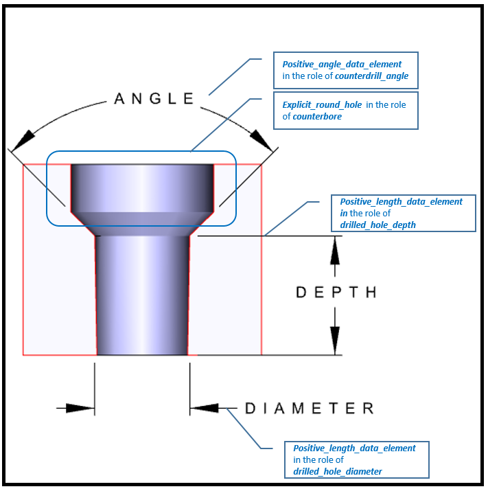
An Md_counterdrill_hole_definition is a type of
Characterizable_object
that defines a template to structure the requirements for a counterdrill hole.
NOTE 6
When applicable see ASME Y14.5-2009[2].
NOTE 7
See Figure 4 for an illustration of the attributes.
Figure 4 — Md_counterdrill_hole_definition attributes
EXPRESS specification:
            *)

            ENTITY Md_counterdrill_hole_definition

              SUBTYPE OF (Explicit_composite_hole);


              counterbore : Explicit_round_hole;


              counterdrill_angle : Positive_angle_data_element;


              counterdrill_angle_tolerance :
            OPTIONAL
            Angle_plus_minus_bounds;


              drilled_hole_depth :
            OPTIONAL
            Positive_length_data_element;


              drilled_hole_depth_tolerance :
            OPTIONAL
            Length_plus_minus_bounds;


              drilled_hole_diameter : Positive_length_data_element;


              drilled_hole_diameter_tolerance :
            OPTIONAL
            md_tolerance_value_or_limits_and_fits;


              through_hole : BOOLEAN;


              shape_model : Geometric_model;
WHERE

              WR1: through_hole XOR EXISTS(drilled_hole_depth);

            END_ENTITY;
(*
Attribute definitions:
counterbore:
specifies the bore that helps compose an Md_counterdrill_hole_definition.
counterdrill_angle:
specifies the required angle for the counterdrill.
counterdrill_angle_tolerance:
specifies the tolerance of the counterdrill angle specification.
drilled_hole_depth:
specifies the required depth of the drilled hole. The value of this attribute need not be specified.
drilled_hole_depth_tolerance:
specifies the tolerance of the drilled_hole_depth. The value of this attribute need not be supplied.
drilled_hole_diameter:
specifies the required diameter of the drilled hole.
drilled_hole_diameter_tolerance:
specifies the
that provides the required diameter of the drilled hole.
through_hole:
specifies that the depth of the smaller hole is completely through the item.
shape_model:
a shape_ model that contains as a minimum an
Axis_placement_3d
that is a placement origin for orientation and position.
Formal propositions:
WR1:
The member of Md_counterdrill_hole_definition provided shall specify that the hole is drilled completely through the item
or it shall specify a depth; however, the member of Md_counterdrill_hole_definition provided shall not specify that the hole is
drilled completely through the item and specify a depth.
A Simplified_md_counterdrill_hole_definition is a type of
Md_counterdrill_hole_definition
that provides the minimal or no geometric definition for the hole.
EXPRESS specification:
            *)

            ENTITY Simplified_md_counterdrill_hole_definition

              SUBTYPE OF (Md_counterdrill_hole_definition);


              SELF\Md_counterdrill_hole_definition.shape_model RENAMED position : Geometric_model;
WHERE

              WR1: SIZEOF(position\Geometric_model.items) = 1;

            END_ENTITY;
(*
Attribute definitions:
position:
specifies a geometric model that includes the placement origin for the hole definition.
Formal propositions:
WR1:
There shall be exactly one item in the shape_model specified by position.
An Md_counterdrill_hole_occurrence is a type of
Shape_element
that is an application of the definition in the design context.
EXPRESS specification:
            *)

            ENTITY Md_counterdrill_hole_occurrence

              SUBTYPE OF (Shape_element);


              definition : Md_counterdrill_hole_definition;
WHERE

              WR1: 'PART_VIEW_DEFINITION_ARM.PART_VIEW_DEFINITION' IN TYPEOF(SELF\Shape_element.associated_definition);

              WR2: SELF\Shape_element.product_definitional = TRUE;

            END_ENTITY;
(*
Attribute definitions:
definition:
specifies the property values of the counterdrilled_hole.
Formal propositions:
WR1:
the counterdrill_hole_occurence shall be associated with a product_view_definition.
WR2:
the placement of the hole shall be on the surface of the item.
An Md_counterdrill_hole_occurrence_in_assembly is a type of
Md_counterdrill_hole_occurrence
that is associated with a product definition that is an assembly.
EXPRESS specification:
            *)

            ENTITY Md_counterdrill_hole_occurrence_in_assembly

              SUBTYPE OF (Md_counterdrill_hole_occurrence);


              modified_components : LIST[1:?] OF
            UNIQUE
            Multi_level_reference_designator;

            END_ENTITY;
(*
Attribute definitions:
modified_components:
specifies the components the hole penetrates.
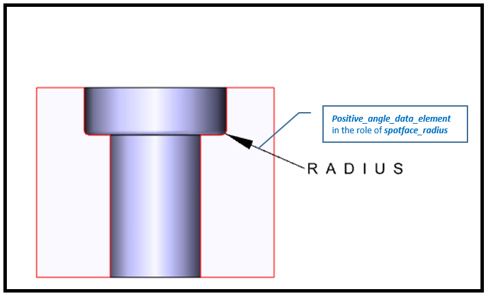
A Spotface_definition is a type of
Explicit_round_hole
in which a radius is applied to the bottom surface of the outside diameter.
NOTE 8
When applicable see ASME Y14.5-2009[2].
NOTE 9
See Figure 5 for an illustration of the attributes.
Figure 5 — Spotface_definition attributes
EXPRESS specification:
            *)

            ENTITY Spotface_definition

              SUBTYPE OF (Explicit_round_hole);


              spotface_radius : Positive_length_data_element;


              spotface_radius_tolerance :
            OPTIONAL
            Length_plus_minus_bounds;

            END_ENTITY;
(*
Attribute definitions:
spotface_radius:
specifies the required fillet radius on the bottom of the larger hole.
spotface_radius_tolerance:
specifies the tolerance of the specified fillet radius.
The value of this attribute need not be supplied.
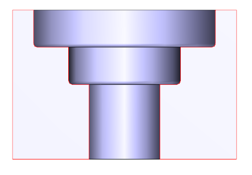
A Spotface_hole_definition is a type of
Md_counterbore_hole_definition
in which a radius is applied to the bottom surface of each bore.
NOTE 10
When applicable see ASME Y14.5-2009[2].
NOTE 11
See Figure 6 for an illustration of a multibore Spotface_hole_definition.
Figure 6 — Multibore Spotface_hole_definition
EXPRESS specification:
            *)

            ENTITY Spotface_hole_definition

              SUBTYPE OF (Md_counterbore_hole_definition);


              SELF\Md_counterbore_hole_definition.counterbore_definition RENAMED spotface : LIST[1:?] OF
            UNIQUE
            Spotface_definition;

            END_ENTITY;
(*
Attribute definitions:
spotface:
specifies the list of bores that make up a compound spotface hole, arranged by ascending order of diameter.
A Simplified_spotface_hole_definition is a type of
Spotface_hole_definition
and
Simplified_md_counterbore_hole_definition
that provides the minimal or no geometric definition for the hole.
EXPRESS specification:
            *)

            ENTITY Simplified_spotface_hole_definition

              SUBTYPE OF (Spotface_hole_definition, Simplified_md_counterbore_hole_definition);

            END_ENTITY;
(*
A Spotface_occurrence is a type of
Md_counterbore_hole_occurrence
that is an application of the definition in the design context.
EXPRESS specification:
            *)

            ENTITY Spotface_occurrence

              SUBTYPE OF (Md_counterbore_hole_occurrence);


              SELF\Md_counterbore_hole_occurrence.definition : Spotface_hole_definition;

            END_ENTITY;
(*
Attribute definitions:
definition:
specifies the Spotface_hole_definition
that provides the parametric data values and geometric reference data values of the
Spotface_occurrence.
A Spotface_occurrence_in_assembly is a type of
Md_counterbore_hole_occurrence_in_assembly
that is associated with a product definition that is an assembly.
EXPRESS specification:
            *)

            ENTITY Spotface_occurrence_in_assembly

              SUBTYPE OF (Md_counterbore_hole_occurrence_in_assembly);


              SELF\Md_counterbore_hole_occurrence.definition : Spotface_hole_definition;

            END_ENTITY;
(*
Attribute definitions:
definition:
specifies the Spotface_hole_definition
that provides the parametric data values and geometric reference data values of the
Spotface_occurrence_in_assembly.
A Mechanical_design_requirement_item_association is a type of
Item_identified_representation_usage
that assigns a requirement to the product manufacturing information.
EXPRESS specification:
            *)

            ENTITY Mechanical_design_requirement_item_association

              SUBTYPE OF (Item_identified_representation_usage);


              requirement : Requirement_assignment;

            END_ENTITY;
(*
Attribute definitions:
requirement:
specifies the assigned requirement to the PMI definition.
This subclause specifies the ARM function for
this module. The ARM function and definition is
specified below.
Axis_placement_3d
The get_the_placement function returns the set of
Axis_placement_3d
associated with the
Geometric_model
as an input.
EXPRESS specification:
         *)

         FUNCTION get_the_placement (input : Geometric_model) : Axis_placement_3d;
  LOCAL
  ap : SET OF Axis_placement_3d := QUERY(ri
                                         <* input\Geometric_model.items
                                         | ('ELEMENTAL_GEOMETRIC_SHAPE_ARM.AXIS_PLACEMENT_3D' IN TYPEOF(ri)));
    END_LOCAL;
      RETURN(ap[LOINDEX(ap)]);
         END_FUNCTION;

(*
Argument definitions:
input:
the specified
Geometric_model.
         *)

         END_SCHEMA;  -- Mechanical_design_features_and_requirements_arm
(*
© ISO 2021 — All rights reserved