Geometry Translation
CAD model exchange was the original application for the STEP standard and still the core capability. We have provided solutions to the data exchange teams within many CAD companies to interface between their internal structures and the STEP definitions.
The range of definitions within the STEP standards is extensive (over 1900 at last count) and we provide software support and expertise for reading, validating, and interpreting existing models or for populating new models from your existing geometry.
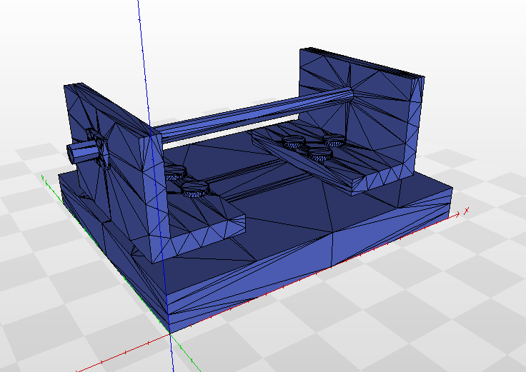
Most CAD models use boundary representation solids, but we can also apply our STEP faceting technology to models to create meshed geometry for lightweight viewing or for use by additive manufacturing systems.
STEP models can hold more than just geometry. Tolerances/PMI, assembly structure, configuration management, design owners, approvals, presentation (colors, layers, groups), and kinematics may all be associated with the CAD shape.
Background
STEP APs
The content of STEP CAD models is described by ISO standards called Application Protocols (APs). AP203 and AP214 cover CAD geometry and assemblies. AP242 adds tolerances/PMI, new geometry types, and soon additive manufacturing setups. AP238 adds Digital Thread manufacturing process.
STEP Geometry
STEP geometry and topology definitions cover just about every mathematical curve and surface ever used in CAD systems. For low-level translation work, our solutions can expose curves, surfaces and faces as individual programming objects. High-level translations can work with complete solids, and we can handle the details.
STEP Exchange Files
The file format for STEP models is a different ISO standard, called Part 21, and can hold content from any AP. The latest 2016 version of the spec can build large CAD models from networks of remote resources.
Legal notices and trademarks.