Description
The EXPRESS-G Layout tool will take syntactically correct EXPRESS text files and convert them to EXPRESS-G diagrams. The diagrams can then be viewed with expgedit or printed using either expg2ps or expg2hpgl.
Command Line
express2expg [options] expfile1 [expfile2 ...]
The options recognized by the diagram layout tool are shown below:
- -help
- Print this list of options. The tool performs no other action and ignores all other options.
- -cuttopage
- Force the layout engine to break definitions into pieces small enough to fit on a single page (where possible). This is useful for printed diagrams, but for interactive viewing it is more useful to preserve the full inheritance tree structure without the extra page breaks this creates.
- -diagonals
- Allow the layout engine to use diagonal lines. By default, the engine uses a Manhattan layout (all lines at right angles).
- -direct
- Direct inter-schema links. Normally, express2expg will attempt to keep schema's independent by inserting inter-schema references. This option will force the tool to link objects directly where possible. Because the diagrams may be spread out, this tends to just replace the inter-schema references with page breaks. Use the -nobreak or -farbreak options to disable page breaks.
- -farbreak
- Don't insert a page break if objects are "close." When arranging a diagram, the tool inserts page breaks to avoid long crossing lines. This option forces direct connections instead of page breaks, for objects that are near one another. This is useful for smaller schemas, where it is possible to work with most of the schema at once. Note, however, that a large number of lines can slow down display with the expgedit editor.
- -fontname <name>
- Set the font for printing. The default is Helvetica-Bold. In order for express2expg to properly layout the boxes for printing it needs to have a description of the font. On UNIX systems we use font metrics files that are freely available from Adobe. See UNIX Technical Notes for more information about obtaining, and adding font metrics files to your installation.
- -fontsize <point-size>
- Set font size for printing. The default is 7 pt. text. This can be too small for some purposes, but is quite readable, and reproducible on a 300dpi printer. Due to limitations in X11, the full scale view of your document will always use a 10 pt. font. Page breaks and boxes will be scaled according to this value.
- -fulltree
- Keep inheritance trees full. The express2expg tool normally breaks up wide inheritance trees by inserting page breaks. You may want to use this option when preparing EXPRESS-G diagrams for printing with either expg2ps or expg2hpgl.
- -i / -index
- Print an index listing for every definition in the diagram. The name of each definition is printed, along with the number of the page it is defined on. The expginfo tool can also produce such a listing. See EXPRESS-G Diagram Information for an example.
- -l / -landscape
- Swap the x and y dimensions of the page. For example, if you had 8.5x14 (legal-sized printer) paper, and wanted landscape mode you would use: express2expg -pagewidth 7.5 -pageheight 13 -l
- -nobreak
- Do not insert page breaks in the diagram. This is only useful on rather small schemas.
- -pagesize <std-size>
- Select one of the standard ANSI paper sizes A, B, C, D, E, or or ISO paper sizes A0-A4
- -pageheight <height-in-inches>
- Set the size in inches of the height of the page. The default is 10.0". See -pagewidth above for some warnings as to its use.
- -pagewidth <width-in-inches>
- Set the size in inches of the width of the page. The default is 7.5". If you have a printer that takes larger paper you may wish to change this. Note that you often need to leave a margin around the page where the printer is incapable of printing.
- -ref <num>
- Change the starting number of the page references. Page references will start at <num> and increase by 1. Note that page references are not the same as page numbers. Each page reference has a unique number within the EXPRESS-G diagram. This offers a way to have unique page references through multiple EXPRESS-G diagrams.
- -v
- Verbose mode will give more information about the conversion process, such as messages from the EXPRESS compiler. It is also useful for tracking the progress through large schemas.
- -workingset <namefile>
- Generate EXPRESS-G for the subset of entities in a working set. Reads a list of names from <namefile> and creates diagrams for just those entities and supporting types. Useful when working with a few types or entities from a large APs. See Customizing Output with a Working Set File for a description of working sets.
Windows Control Panel
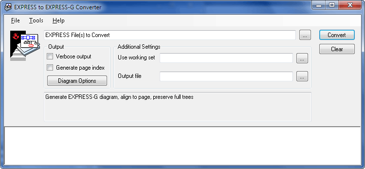
The EXPRESS-G Layout Windows control panel is shown below. Run this by selecting EXPRESS-G to EXPRESS-G on the Start Menu. The following sections describe fields and setting on this control panel and show how to control the converter.

Generating Diagrams
At the top of the EXPRESS-G Layout control panel is a text field for one or more schema files that you would like to convert. You can open the file dialog using Ctrl+O or the [...] button to the right. You can also drag and drop files from the Windows Explorer.
The Use working set field or -ws command line option can specify a file containing a subset of definitions that should appear in the diagram. For more information on working sets see the ROSE Library Reference Manual .
The Output file field or -f command line option provide the name of the resulting EXPRESS-G diagram file. If do not specify the name of the output file, the diagram file will be the same as the first EXPRESS file, but with the `.exg' extension.
The Verbose output option or -v flag make the tool display more information about the conversion process and messages from the EXPRESS compiler.
The Generate page index option or -index flag prints an index which lists the location of all definitions.
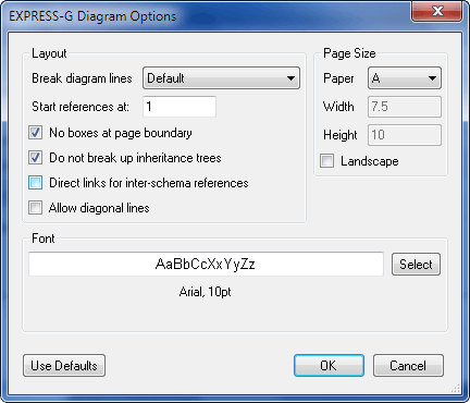
The Diagram Options button brings up the dialog shown below, with additional options for controlling the layout process. In the Layout area the Break diagram lines menu controls how long lines are separated by page references. The Only between far objects choice and -farbreak flag insert fewer page reference boxes, while the Never choice and -nobreak flag insert no page references.

The Start references at field and -ref command line option give a numeric starting value for the references boxes in the diagram. References start at this number and increase by 1. Each page reference has a unique number within an EXPRESS-G diagram. This offers a way to keep unique references through multiple diagrams.
The No boxes at page boundary option or the -cuttopage flag breaks up definitions until they are small enough to fit on a single page (where possible).
The Do not break up inheritance trees option or the -fulltree flag keeps inheritance trees full. Use this option to create wall-sized EXPRESS-G diagrams for printing.
The Direct links for inter-schema references option or the -direct flag forces the tool to link objects directly where possible. Normally, the layout engine attempts to keep schemas independent by inserting inter-schema references.
The Allow diagonal lines option or the -diagonal flag removes the restriction on the connecting lines to horizontal and vertical (Manhattan style) layout.
The Page Size area describes the paper to assume when placing and grouping the diagram elements. The Paper field or -pagesize option selects from a list of standard ANSI and ISO paper sizes. The Width / Height fields or -pagewidth / -pageheight flags are used for custom page sizes. The Landscape option or -landscape flag swaps the height and width page dimensions.
The Font field or -fontname / -fontsize flags specify the font to be used by the diagram. The options dialog shows a sample of the font. Click the Select button to pick a font using the Windows font dialog.
Layout Style
The layout engine considers the inheritance hierarchy first, and will arrange definitions so that references to an entity come in from the top and references to sub-types are placed at the bottom of an entity. Attributes will be placed at the sides of each entity.
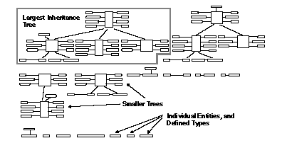
On the virtual page, the largest inheritance trees are placed first. The converter proceeds from left to right, top to bottom across the virtual page. The largest tree is in the upper left hand corner and the smallest is at the bottom, as shown below. The smallest objects tend to be defined types, selects, enumerations or unused entities.

The default layout style is useful for learning or comparing EXPRESS schemas. By default the tool will try to keep the inheritance trees whole. The tool inserts a page reference or an inter-schema reference when ever it is unable to put the actual entity in that location. The tool disregards page boundaries when placing entities.
You may wish to change the defaults when preparing diagrams for printed documentation. For instance, use the -cuttopage option to break the diagram into page-sized pieces.
UNIX Technical Notes
The UNIX EXPRESS-G tools use Adobe font metrics files to calculate basic information about the font sizes. Without a proper font metrics file express2expg will tend to generate a poor layout. Adobe provides font metrics files via anonymous FTP (ftp://ftp.adobe.com/pub/adobe/type/). We have included files for Helvetica, Times, and Courier in normal, italic, bold and bold&italic styles. The files are installed in $ROSE/lib/afm.
The EXPRESS-G tools will check for the desired font metrics file in the following places:
    $ROSE_AFM  (a list of colon separated directories to check)
    $HOME
    $HOME/afm
    $ROSE/system_db/afm