
| Integrated generic resource: Shape variation tolerances | ISO 10303-47:2021(E) © ISO |
The shape_dimension_schema provides a representation for the description of location and size dimensions. The measure of a dimension may be either assigned to or derived from other shape_aspect elements. The supported types of measurement path for applying a dimension are:
Each implementation of an AP that uses this schema and that encodes entity names shall use the encoding specified in Annex A. Each reference to this schema in an open system shall use the identifier encoding specified in Annex B. This schema is illustrated in Annex D using the EXPRESS-G notation.
EXPRESS specification:
         *)

            	SCHEMA shape_dimension_schema;
            REFERENCE FROM
            basic_attribute_schema

               --
            ISO 10303-41
  (get_id_value,


            id_attribute,


            id_attribute_select);
            REFERENCE FROM
            measure_schema

               --
            ISO 10303-41
  (measure_with_unit);
            REFERENCE FROM
            product_property_definition_schema

               --
            ISO 10303-41
  (shape_aspect,


            shape_aspect_relationship);
            REFERENCE FROM
            product_property_representation_schema

               --
            ISO 10303-41
  (item_identified_representation_usage_definition,


            shape_representation);
            REFERENCE FROM
            qualified_measure_schema

               --
            ISO 10303-45
  (descriptive_representation_item,


            measure_representation_item,


            qualified_representation_item);
            REFERENCE FROM
            representation_schema

               --
            ISO 10303-43
  (representation,


            compound_representation_item);
            REFERENCE FROM
            support_resource_schema

               --
            ISO 10303-41
  (identifier,


            label,


            text);
            REFERENCE FROM
            geometry_schema

               --
            ISO 10303-42
  (placement);

(*
NOTE 1 The schemas referenced above are specified in the following parts:
basic_attribute_schema ISO 10303-41 measure_schema ISO 10303-41 product_property_definition_schema ISO 10303-41 product_property_representation_schema ISO 10303-41 qualified_measure_schema ISO 10303-45 representation_schema ISO 10303-43 support_resource_schema ISO 10303-41 geometry_schema ISO 10303-42
NOTE 2 See Annex D for a graphical representation of this schema.
Dimensions that are derived from the geometric representations of shape_aspects are considered to be implicitly defined. Dimensions that are assigned to a shape_aspect, which may or may not have associated geometric representation, are considered to be explicitly defined. A size or location dimension may be both implicitly and explicitly defined for a given shape_aspect.
NOTE 1 The lower limit of a limit dimension can be represented by either an explicit or assigned, dimension, while the upper limit value may be on an implicit or explicit dimension.
NOTE 2 Legal values that are computer sensible for attributes of entities in this schema may be specified in application protocols.
This part of ISO 10303 does not distinguish between intended values (e.g., designed values) and actual values (e.g., measured values) for either dimensions or tolerances. Geometrical tolerances and plus-minus tolerances may be applied to a dimension. Dimensions need not have a tolerance value.
This part of ISO 10303 does not distinguish between uses of dimensions. Uses of dimensions are defined in application protocols using this part of ISO 10303.
EXAMPLE The specification of a dimension to define the desired product shape and the specification of a dimension to describe as-manufactured product shape are two uses of dimension.
This part of ISO 10303 provides for the representation of dimensions in a manner that is independent of any requirements for draughting presentation.
NOTE 3 The application and use of basic dimensions or reference dimensions are specified in an application protocol.
A dimensional_location is a relationship between two shape_aspect elements that identifies a spatial constraint that shall be maintained during any physical transformation, translation, or rotation of the shape_aspect elements together. This relationship is either directed from the origin shape_aspect or datum to the target shape_aspect, or it is non-directed. Only non-directed dimensional location is addressed in this part of ISO 10303.
NOTE 4 The decision as to whether the dimensional_location is directed or non-directed is specified in an application protocol.
A dimensional_size of a shape_aspect identifies a constraint between the relative position of the boundary of the shape_aspect with either its axis of symmetry or another boundary of the same shape_aspect. The dimensional_size is unaffected by any translation or rotation of the shape_aspect.
A dimension is applied along a specific measuring path. When the measuring path is not explicitly identified, the dimension will apply along an implicit path. The definition of an implicit measuring path is dependent on the context of use and is specified in an application protocol.
Unless otherwise specified dimensions shall be interpreted in accordance with ISO 8015, ISO/TS 17450-1, ISO/TS 17450-2, ISO 14405-1 and ISO 14405-2.
NOTE 5 Alternatively dimensions can be used according to the specifications given in ASME Y14.5-2009 [11].

An angle_relator type is an identification of an angle. This angle is one of a set of possible angles created by:
EXPRESS specification:
            *)

            TYPE
            angle_relator
            =

            ENUMERATION

            OF


            (equal,
    large,
    small);

            END_TYPE;

            (*
Enumerated item definitions:
equal: the numerical measure of the angles is equal at the point of intersection between two shape_aspect elements.
large: the numerical measure of the selected angle at the point of intersection between two shape_aspect elements are the larger absolute value.
small: the numerical measure of the selected angle at the point of intersection between two shape_aspect elements are the smaller absolute value.
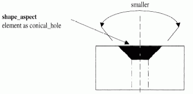
EXAMPLE Figure 8 illustrates a type of single angular shape_aspect. See figure 9 for types of intersections of shape_aspects.

EXPRESS specification:
            *)

            TYPE
            dimensional_characteristic
            =


            SELECT

               (dimensional_location,
    dimensional_size);

            END_TYPE;

            (*

EXPRESS specification:
            *)

            TYPE
            sd_id_attribute_select
            =


            SELECT
            BASED_ON
            id_attribute_select
            WITH


               (dimensional_size);

            END_TYPE;

            (*

NOTE The list of entity data types will be extended in application resources that use the constructs of this resource.
EXPRESS specification:
            *)

            TYPE
            sds_item_identified_representation_usage_definition
            =

            EXTENSIBLE

            GENERIC_ENTITY


            SELECT
            BASED_ON
            item_identified_representation_usage_definition
            WITH


               (dimensional_size);

            END_TYPE;

            (*

EXPRESS specification:
            *)

            TYPE
            shape_dimension_representation_item
            =


            SELECT

               (compound_representation_item,
    descriptive_representation_item,
    measure_representation_item,
    placement);

            END_TYPE;

            (*

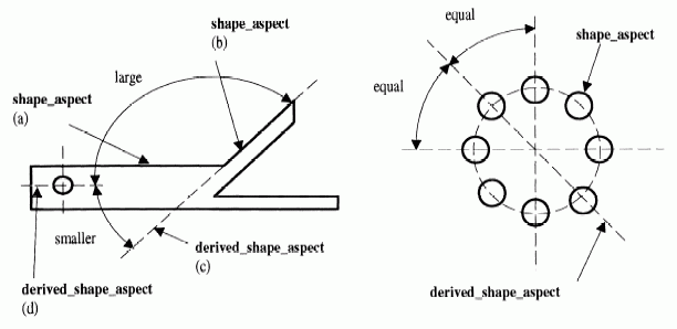
An angular_location is a type of dimensional_location. An angular_location specifies that a spatial constraint exists between two shape_aspect elements that intersect or would intersect if projected. An angular_location is a measure of the angle defined by the two shape_aspect elements and their common intersection or projected intersection.
NOTE The application and use of an angular_location is illustrated in Figure 9. Figure 9 also illustrates types of intersection of two shape_aspect elements( a and b) and virtual intersection formed by derived_shape_aspects (c and d).
EXPRESS specification:
            *)

            ENTITY angular_location

              SUBTYPE OF (dimensional_location);


              angle_selection : angle_relator;

            END_ENTITY;
(*
Attribute definitions:
angle_selection: an indication of the specific angle type at the point of intersection.

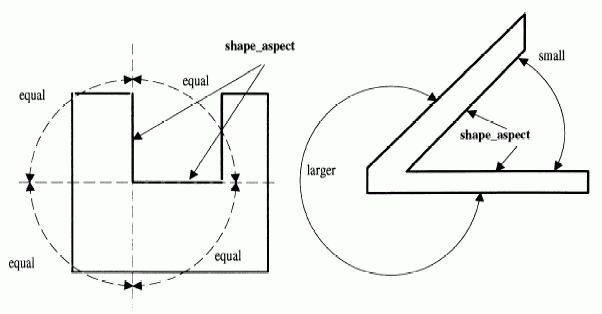
An angular_size is a type of dimensional_size. An angular_size size is the measure of the angle formed by two boundaries of the shape_aspect and their common or projected intersection. An angular_size defines an angular spatial characteristic of a shape_aspect. An angular_size is represented by a single magnitude and is independent of the location of the shape_aspect on or within the product.
NOTE The application and use of an angular_size is illustrated in figure 10.
EXPRESS specification:
            *)

            ENTITY angular_size

              SUBTYPE OF (dimensional_size);


              angle_selection : angle_relator;

            END_ENTITY;
(*
Attribute definitions:
angle_selection: an indication of the specific type of angle at the point of intersection.

A dimensional_characteristic_representation is an association of an implicit dimension with an explicit non-geometric representation.
NOTE A dimension for a shape_aspect may be explicitly represented as an actual value, a scaled value, a precision dependent value, or a pair of values that specify the upper and lower size limits. A dimensional_characteristic_representation associates one of the above value types with the implicit dimension value that may be derived from the geometric representation of the shape_aspect.
EXPRESS specification:
            *)

            ENTITY dimensional_characteristic_representation;


              dimension : dimensional_characteristic;


              representation : shape_dimension_representation;

            END_ENTITY;
(*
Attribute definitions:
dimension: an implicit measurement for which an explicit non-geometric representation is defined.
representation: the explicit non-geometric representation assigned to the dimension.

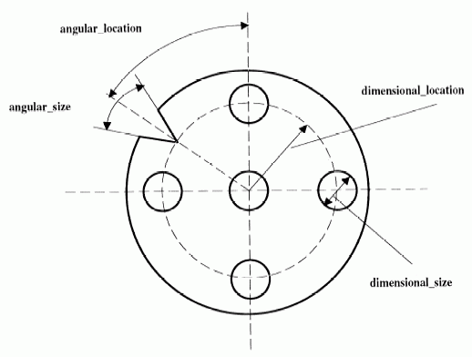
A dimensional_location is a type of shape_aspect_relationship. A dimensional_location specifies that a spatial constraint exists between two shape_aspect elements that are represented as a non-directed measure applied along a measurement path. A dimensional_location may be either an angular_location or a dimensional_location_with_path.
NOTE 1 Representation of a shape_aspect participating in the dimensional_location relationship implies a measuring direction for the dimensional_location through the related and relating shape_aspect. The meaning of the direction is specified in an application protocol.
NOTE 2 The application and use of dimensional_location and dimensional_size are shown in figure 11.
EXPRESS specification:
            *)

            ENTITY dimensional_location

              SUPERTYPE OF (ONEOF (angular_location,
                       dimensional_location_with_path))

              SUBTYPE OF (shape_aspect_relationship);
WHERE

              WR1: SELF\shape_aspect_relationship.relating_shape_aspect :<>: SELF\shape_aspect_relationship.related_shape_aspect;

              WR2: SELF\shape_aspect_relationship.relating_shape_aspect.of_shape :=: SELF\shape_aspect_relationship.related_shape_aspect.of_shape;

            END_ENTITY;
(*
Formal propositions:
WR1: The relating and related shape_aspect shall be different.
WR2: The relating and related shape_aspect shall refer to the same instance of product_definition_shape.

A dimensional_location_with_path is a type of dimensional_location. A dimensional_location_with_path specifies that a spatial constraint exists between two shape_aspect elements along an explicit path. The dimensional_location_with_path is a dimensional_location applied along an explicit path that is defined between the shape_aspect elements.
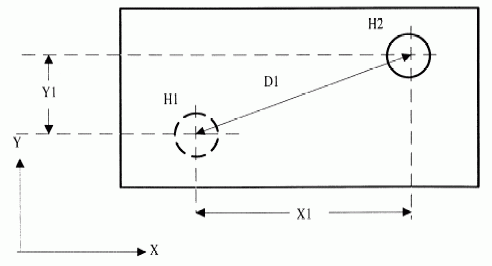
EXAMPLE See figure 12. The location of hole H2 from hole H1 may be defined with either dimensional_locations, X1 and Y1 or, dimensional_location_with_path, D1. Dimensional_locations X1 and Y1 use implicit measuring paths defined by a coordinate system associated with the product. A dimensional_location_with_path applies along the explicit measuring path defined by the line intersecting the centres of the 2 holes.
EXPRESS specification:
            *)

            ENTITY dimensional_location_with_path

              SUBTYPE OF (dimensional_location);


              path : shape_aspect;

            END_ENTITY;
(*
Attribute definitions:
path: the shape_aspect defining the measurement path for the dimension.

EXPRESS specification:
            *)

            ENTITY dimensional_size

              SUPERTYPE OF (ONEOF (angular_size,
                       dimensional_size_with_path));


              applies_to : shape_aspect;


              name : label;
DERIVE

              id : identifier := get_id_value(SELF);
UNIQUE

              UR1: id, applies_to;
WHERE

              WR1: applies_to.product_definitional = TRUE;

              WR2: SIZEOF(USEDIN(SELF, 'BASIC_ATTRIBUTE_SCHEMA.' + 'ID_ATTRIBUTE.IDENTIFIED_ITEM')) <= 1;

            END_ENTITY;
(*
Attribute definitions:
applies_to: the shape_aspect being dimensioned.
name: the identification of the application use of the dimension.
EXAMPLE A size characteristic may be either a radius, a diameter, a length constraint, an angular constraint, a curve shape_aspect, an axisymmetric shape_aspect, or a circular shape_aspect. Use of the name attribute with a value of “radius” clarifies the application use of this dimension.
id: the identifier that distinguishes the dimensional_size.
Formal propositions:
UR1: The id shall be unique for the applied shape_aspect.
WR1: A dimensional_size shall lie on the physical boundary of the shape that defines the product.
WR2: Each dimensional_size shall be the identified_item in at most one id_attribute.

EXPRESS specification:
            *)

            ENTITY dimensional_size_with_path

              SUBTYPE OF (dimensional_size);


              path : shape_aspect;

            END_ENTITY;
(*
Attribute definitions:
path: the shape_aspect defining the measurement path for the dimension.

EXPRESS specification:
            *)

            ENTITY directed_dimensional_location

              SUBTYPE OF (dimensional_location);

            END_ENTITY;
(*

A shape_dimension_representation is a type of shape_representation. A shape_dimension_representation is a representation of either dimensional_location or dimensional_size. It is a representation that explicitly describes a dimension of a shape_aspect with either a value or a range of values and needed specification modifiers. Unless otherwise specified the values and specification modifiers shall be used in accordance with ISO/TS 17450-2, ISO 14405-1, and ISO 14405-2.
EXAMPLE 1 A cylindrical shape_aspect is prescribed to have a diameter of 10 centimetres. This specification, “10cm diameter”, is a shape_dimension_representation that defines a size characteristic of the shape_aspect without requiring a geometric representation.
A shape_representation may have many representation_items, but two of the representation_items shall define a specific shape_dimension_representation. Unless otherwise specified upper and lower limits of dimensions shall be used in accordance with ISO 129-1.
EXAMPLE 2 The diameter of a hole is defined to allow a physical instance of the hole to vary between 2.00 cm and 2.01 cm. In the product description, the lower and upper allowable diameters of the hole are represented by a 2.00 cm, geometric cylinder, and another representation item with a value of 2.01 cm.
EXPRESS specification:
            *)

            ENTITY shape_dimension_representation

              SUBTYPE OF (shape_representation);


              SELF\representation.items : SET[1:?] OF shape_dimension_representation_item;

            END_ENTITY;
(*
Attribute definitions:
items: an attribute inherited from the shape_representation shall be redeclared as the shape_dimension_representation_item for the shape_dimension_representation. There shall exist at least one shape_dimension_representation_item for the shape_dimension_representation.
         *)

         END_SCHEMA;  -- shape_dimension_schema
(*
© ISO 2021 — All rights reserved