| Integrated generic resource: Product structure configuration | ISO 10303-44:2021(E) © ISO |
E.1 Product structure
Product structure reports are used by industry to describe the composition and structure of a product. Most products are assembled from other assemblies and components. A product structure report provides details about what subassemblies and components are used.
NOTE See definitions in clause 3.
In this annex, examples of three different types of product structure reports are provided. In addition, the use of this part of ISO 10303 to generate these reports is outlined. The focus of the examples is on the product_structure_schema.
E.1.1 Example of a mechanical assembly product
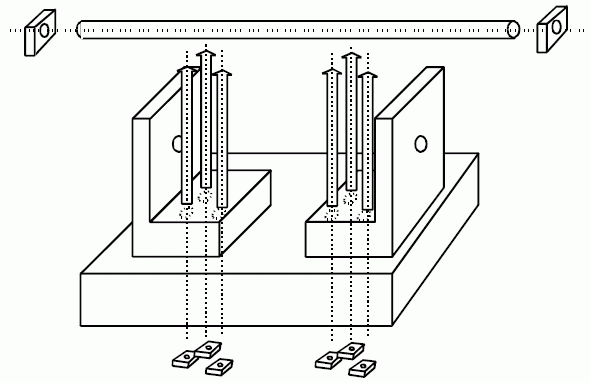
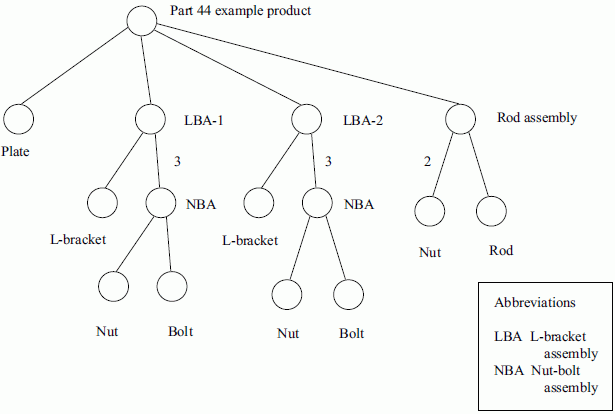
In this section, a hypothetical mechanical assembly product called the "part 44 example product" is described, both in diagrams and in words. This assembly forms the basis for explaining different types of product structure reports, e.g., BOM and parts list, in the next section. This product is modelled using the various entities defined earlier in this part of ISO 10303. See Figure E.2 for the 3D drawing of the "part 44 example product", and Figure E.2 for a diagrammatic representation of the product structure.
The "part 44 example product" represents a simple mechanical assembly consisting of three major constituents: a large metal plate forming the base for attaching two identical L-bracket assemblies. Each of the two L-bracket assemblies is bolted to the base using three nuts and bolts and using three holes drilled into the plate. The L-brackets themselves have a hole drilled in them to support a rod assembly that consists of a threaded rod and nuts attached at each end of the rod. The nuts used on the threaded rod and in the Lbracket assembly are of the same size. This product design has a structure consisting of a number of assemblies, some of which also contain assemblies, i.e., sub-assemblies, as well as a number of individual components.
E.1.2 Examples of product structure reports
Product structure reports can decompose an assembly to many levels of details. The levels of detail can cover the degree of decomposition, the quantities of subassemblies and components used, the position and orientation of the subassemblies and components, and the products used to make other products. The levels of detail include:

Examples of typical reports having a mixture of the characteristics enumerated above are now presented using the "part 44 example product".
E.1.2.1 Example: A numeric, multi-level, indented product structure report
Each assembly, subassembly, and component is placed on a new line. A numeric value, indicating the count or amount of the constituent, may be present. The nesting of the levels is indicated by indentation. Constituents at the same level have the same indentation. This report shows that the "part 44 example product" has two L-bracket assembly units and that each unit contains three nut-bolt assemblies. The rod assembly contains two nuts and a rod.
	Part 44 Example Product
		Plate
		L-bracket assembly (2)
			L-bracket
			Nut-bolt assembly (3)
				Nut
				Bolt
		Rod assembly
			Rod
			Nut (2)
E.1.2.2 Example: A labelled occurrence, multi-level, indented product structure report
In this report, the structure is decomposed to the lowest level of the product structure. A label is assigned to each subassembly and component, down to the lowest level, e.g., Nut-1-1. With this form, all subassemblies and components can be referenced uniquely within the complete product structure and can be distinguished from one another. One can retrieve Nut-2-1 (the first nut on the second L-bracket assembly) and differentiate it from Nut-rod-2 (the second nut on the rod assembly).
	Part 44 Example Product
		Plate-1: Plate
		L-bracket-assembly-1: L-bracket assembly
			L-bracket-1-1: L-bracket
			Nut-bolt-assembly-1-1: Nut-bolt assembly
				Nut-1-1: Nut
				Bolt-1-1: Bolt
			Nut-bolt-assembly-1-2: Nut-bolt assembly
				Nut-1-2: Nut
				Bolt-1-2: Bolt
			Nut-bolt-assembly-1-3: Nut-bolt assembly
				Nut-1-3: Nut
				Bolt-1-3: Bolt
		L-bracket-assembly-2: L-bracket assembly
			L-bracket-2-1: L-bracket
			Nut-bolt-assembly-2-1: Nut-bolt assembly
				Nut-2-1: Nut
				Bolt-2-1: Bolt
			Nut-bolt-assembly-2-2: Nut-bolt assembly
				Nut-2-2: Nut
				Bolt-2-2: Bolt
			Nut-bolt-assembly-2-3: Nut-bolt assembly
				Nut-2-3: Nut
				Bolt-2-3: Bolt
		Rod-assembly-1: Rod assembly
			Rod-1: Rod
			Nut-Rod-1: Nut
			Nut-Rod-2: Nut
E.1.2.3 Example: A numeric, multi-level, extended definition, indented product structure report
This report includes the number of each constituent. This report is an extended definition because it references the product from which some of the components are made; e.g., the sheet metal used to make the plate.
		Part 44 Example Product
			Plate
				Sheet metal
			L-bracket assembly (2)
				L-bracket
					Sheet metal
				Nut-bolt assembly (3)
					Nut
					Bolt
			Rod assembly
				Rod
					Bar stock
				Nut (2)
E.1.3 BOM, parts list, and hybrid data structures
In order for a compliant application to generate the information normally expected in the various product structure reports in the last section, it will need the information to be represented in data structures for physical storage. This example introduces three data structures that may be used to represent this information. They are the BOM data structure, the parts list data structure, and the hybrid data structure that are defined in E.1.3.1, E.1.3.2, and E.1.3.3.
E.1.3.1 BOM data structures
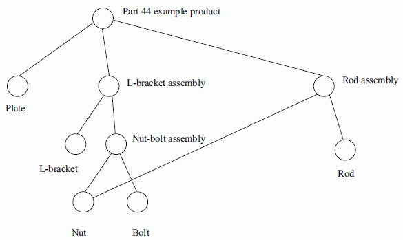
The BOM data structure is used to represent the assembly aspects of product structure. The BOM structure specifies only the different products used in an assembly, and thus provides a list of products necessary to create the assembly. Each of these products, as identified in the structure, is a typical product and is called a definition. Only one definition is included for each kind of product that participates in the structure. Although there are eight nuts specified in the "part 44 example product" above, the BOM data structure representing this structure would have only one nut to represent that kind of product in the "part 44 example product". (See Figure E.3)
The BOM data structure does support the representation of multiple relationships between two specific definitions. To indicate that there are three nut-bolt assemblies in the "part 44 example product", the data structure holds only one instance of the nut-bolt assembly, but three associations connecting it to the parent assembly.
A ramification of this BOM data structure is that the components of each assembly are indistinguishable within any assembly that includes it. Thus, although the L-bracket assembly contains three nut-bolt assemblies, each in turn containing a nut and a bolt, there is no way to distinguish any of the individual bolts or nuts within the L-bracket assembly except through their usage in the assembly.
E.1.3.2 Parts list data structures
The parts list data structure individualizes the relationship between lower-level parts of the product structure and higher-level assemblies in which they are contained.
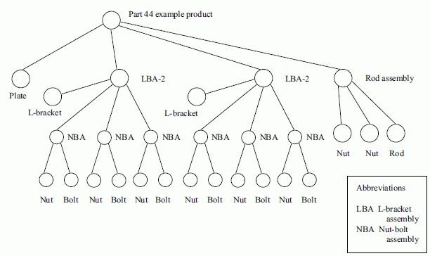
This data structure uses multiple occurrences of the same definition, or typical product, within the data structure at a single time. The representation of the usage of a particular definition is called an occurrence. An occurrence need not specify its definition counterpart. If there are two L-bracket assemblies within the "part 44 example product", the parts list data structure would include two different L-bracket occurrences which then permits the unique identification of the respective components of the L-bracket assemblies within the context of the overall "part 44 example product". Each L-bracket assembly occurrence is based on a typical L-bracket assembly definition that would contain all of the information that characterizes it. This parts list data structure can be seen in Figure E.4, where the L-bracket assemblies and the nut-bolt assemblies are individually represented. Each of these individually represented parts and assemblies are occurrences of a definition of those parts or assemblies. An explicit relationship to the definition could be specified.
E.1.3.3 Hybrid data structures
A hybrid data structure is a mixture of the BOM and parts list data structures. The mixture may have a definition in which the assembly structure lists all the occurrences that comprise its constituents. Conversely, an occurrence may have its constituents described as a single definition with multiple associations to describe each particular usage of the component definition within the assembly. Additionally, each occurrence that comprises an assembly may be decomposed implicitly by the decomposition of its associated definition.
E.1.4 Representation of product structure data structures using ISO 10303-44 entities
The BOM, parts list, and hybrid data structures are mapped into a combination of product_definition and product_definition_relationship (or subtypes) entities. For pure BOM structures, only the quantified_assembly_component_usage, next_assembly_usage_occurrence, or make_from_usage_option subtypes of product_definition_usage need to be used, since the lower-level components are used only as "black boxes" to the parent assembly component. The "part 44 example product" does have two L-bracket assemblies, but from a BOM data structure point of view, these L-bracket assemblies are the same and it is not possible to distinguish their assembly composition. For parts list structures, only the specified_higher_usage_occurrence and next_assembly_usage_occurrence subtypes of product_definition_usage need to be used. In this case each of the L-bracket assemblies will be represented by unique instances of product_definition. For hybrid structures, all of the entities specified for BOM and parts list data structures may be used.
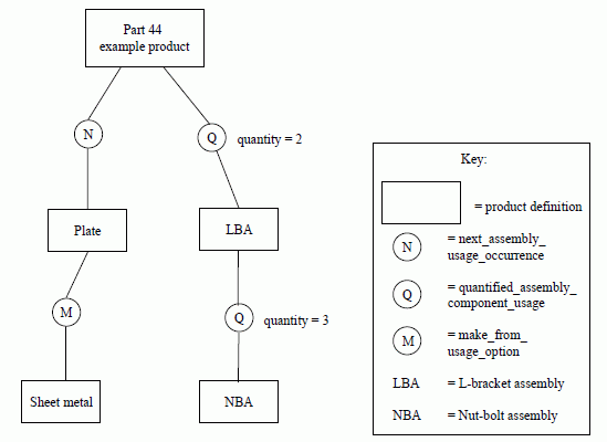
Figures E.5, E.7, and E.12 contain the symbology for the entities in this part of ISO 10303 that is used in figure E.5 the following figures. Rectangles represent instances of the product_definition, and circles represent instances of product_definition_relationship entity or instances of one of its subtypes. The circles are labelled either with the first letter of the specific subtype or with "D-O" for a product_definition_relationship that specifies the relationship between an occurrence and its definition counterpart. In Figure E.5, there are instances of the next_assembly_usage_occurrence (label is "N"), the quantified_assembly_component_usage (label is "Q"), and make_from_usage_option (label is "M") subtypes of product_definition_usage.
E.1.4.1 Representation with definitional BOM structures
For specifying a BOM, two methods can be used to show the quantity of a constituent within an assembly. The quantified_assembly_component_usage subtype of product_definition_usage can be used to specify the count of a component used in the assembly. Figure E.5 contains a subset of the BOM data structure. In the figure, there is a single relationship between the "part 44 example product" and the L-bracket assembly. This relationship is represented using a quantified_assembly_component_usage that specifies a count of two for the L-bracket assembly. Similarly, there is a single relationship between the L-bracket assembly and the nut-bolt assembly. The quantified_assembly_component_usage specifies a count of three for the nut-bolt assembly.
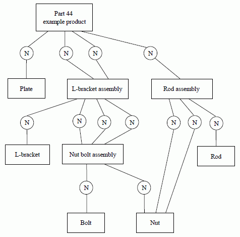
The second method for specifying a BOM involves the identification of each relationship between the component and assembly. Figure E.6 presents the complete model for the "part 44 example product" in a BOM data structure using this part of ISO 10303. Note that individual instances of the next_assembly_usage_occurrence entity represent each use of a component within a higher assembly. The quantity of components in each assembly can be calculated by counting the number of instances of next_assembly_usage_occurrence, rather than using a single instance of quantified_assembly_component_usage that specifies the quantity.
E.1.4.2 Representation with definitional parts list structures
For specifying a parts list with definitional product_definition instances only, the specified_higher_usage_occurrence subtype of product_definition_usage is used in order to make explicit the specific usage of a particular lower-level component within the overall context of a higher assembly. A parts list can specifically identify a sub-component of a lower assembly as distinguished from a similar sub-component of another lower assembly. This is possible because of the additional context information that is provided by the specified_higher_usage_occurrence subtype of product_definition_usage. The additional context information is provided by specifying the specific immediate parent assembly and the specific top-level assembly. For instance, it is possible to identify the bolt on the third nut-bolt assembly of the second L-bracket assembly.
In Figure E.7, the additional information needed to define a parts list is represented by the additional subtype of product_definition_usage, namely the specified_higher_usage_occurrence entity, represented symbolically by the circle with label "S". Here, the specified_higher_usage_occurrence entity allows a reference to one specific nut-bolt assembly on only one of the two L-bracket assemblies. This is accomplished by having the specified_higher_usage_occurrence entity relate to only one of the two usages of the L-bracket assembly as represented by the next_assembly_usage_occurrence entity.
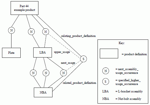
Note that in this example, even though the parts list is implemented using the entities of this part of ISO 10303, it is done without having to create individual instances of the lower-level components. Rather, the additional identifying information is supplied through the existence of the intermediate specified_higher_usage_occurrence and next_assembly_usage_occurrence entities.
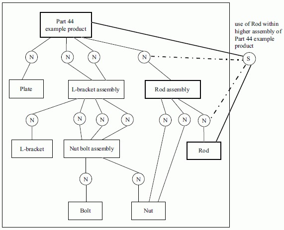
In Figures E.8, E.9, and E.10, the representation of a number of lower-level components (rods, nuts, and assemblies) is presented within the context of higher-level assemblies as they would be represented using the entities of this part of ISO 10303. In each of these figures, the original BOM data structure is included within the large box; the additional entities needed to support the parts list aspects of the examples are placed outside the box, with their attributes referencing the original BOM.
In particular, Figure E.8 highlights the use of a specified_higher_usage_occurrence entity that represents how the Rod is used within the "part 44 example product" as specifically included in a Rod assembly entity. This is an example of a two-level component inclusion and as such, both the upper and next attributes of the specified_higher_usage_occurrence entity refer to next_assembly_usage_occurrence components in the BOM structure.
In Figure E.9, two different cases are represented. In one case, two specified_higher_usage_occurrence entities, located towards the top of the diagram, are included to represent the two nuts that are specifically used within the Rod assembly part of the "part 44 example product". Note that the extra relationship lines to the top-level "part 44 example product" definition and the low-level nut definition have not been included so as not to clutter up the diagram. In the other case, a specified_higher_usage_occurrence entity is used to represent one specific nut within an L-bracket assembly. Again, in both of these cases, only a two-level relationship between component and assembly is being represented and therefore the intermediate product_definition_usage entities are both next_assembly_usage_occurrences.
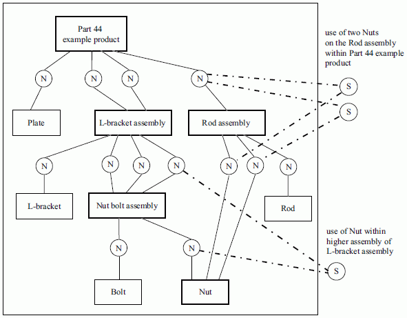
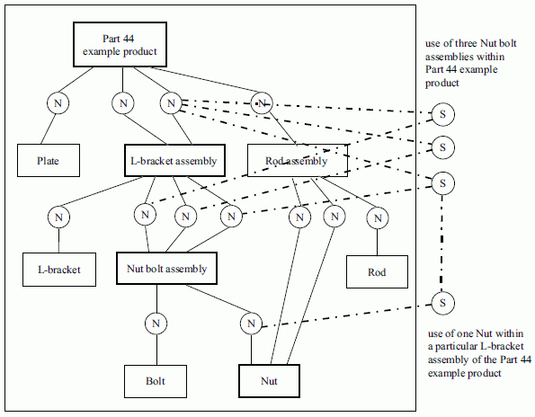
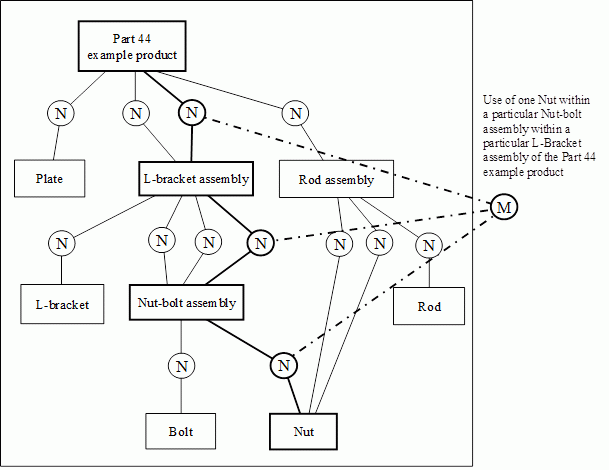
Figure E.10 demonstrates two additional cases of parts list representation using a BOM data structure. First, three specified_higher_usage_occurrence entities are shown to relate the three different nut-bolt assemblies within the overall "part 44 example product". The second case shows a specified_higher_usage_occurrence entity being used to represent one specific nut within a specific nut-bolt assembly within a specific L-bracket assembly of the overall "part 44 example product". This latter use of specified_higher_usage_occurrence entity models a three-level structural relationship between one specific nut and the overall product. As such the associated specified_higher_usage_occurrence entity has its upper attribute referring to another specified_higher_usage_occurrence entity, namely, the entity that identifies the particular usage of the nut-bolt assembly within a particular L-bracket assembly. This way, a recursive structure of specified_higher_usage_occurrences is being created from the lower to the upper levels
The increasing complexity of the parts list representation is a reflection of the complexity of the information within the data structure being managed. In fact, the increasing number of specified_higher_usage_occurrence entities that would be included in a more complete model representation is directly proportional to the number of possible paths that could be navigated through the parts list data structure model as seen in Figure E.7. What has been eliminated through the specification of a BOM data structure are the individual instances of each component, being replaced by individual specified_higher_usage_occurrence entities as required for a particular communication that provide multiple interconnections between a component and a higher-level assembly in which it is located.
An alternative approach to using a recursive chain of specified_higher_usage_occurrences is to use a multi_level_reference_designator. It defines a list of next_assembly_usage_occurrences which specify the intended occurrence of the next-level part for every level of the assembly structure, resulting in an unambiguous path from top (i.e. highest level assembly definition) to bottom (i.e. lowest level part occurrence). A particular usage of the nut within the context of the “part 44 example product” can thus be specified by creating a multi_level_reference_designator with a location list that contains first the next_assembly_usage_occurrence for the second L-bracket assembly in the “Part 44 example product”, next the next_assembly_usage_occurrence for the third Nut bolt assembly in the L-bracket assembly, and finally the next_assembly_usage_occurrence for the nut within the Nut bolt assembly.
E.1.4.3 Representation with occurrence parts list structures
A complete parts list representation of product structure may be specified using the entities in this part of ISO 10303. Figure E.4 depicts a representation of a data structure that captures each occurrence of a particular definition in the product structure. Each circle represents an occurrence of a typical part. Each occurrence is represented by an instance of a product_definition entity. Each product_definition representing an occurrence would, in turn, have a relationship to the definitional product_definition that represents the typical part of which it is an occurrence. Each line represents an instance of next_assembly_usage_occurrence.
When the product structure is completely represented in this fashion, it may be traversed to reach any particular occurrence of a product in the structure. No specified_higher_usage_occurrence instances are required because at any level, data may be associated directly with the individual instance of product_definition that represents the particular occurrence of that product within the product structure.
E.1.4.4 Representation with hybrid structures
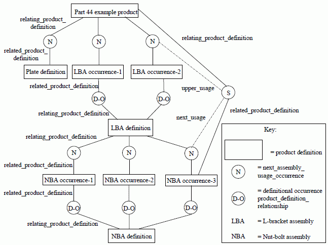
A hybrid structure may be created in which BOM and parts list representations are mixed to provide the capability to specify definitions and occurrences as required. Figure E.12 depicts a hybrid structure using a portion of the product structure of the "part 44 example product". Each definition and occurrence is specified by an instance of product_definition. In the figure, the definition of the "part 44 example product" consists of the definition of the plate and two occurrences of the L-bracket assembly. Each occurrence of the L-bracket assembly is related to the single BOM definition of the L-bracket assembly by an instance of product_definition_relationship, represented symbolically by the circle with label "DO" that specifies it as a definitional occurrence. The definition of the L-bracket assembly is then specified using a parts list structure for the nut-bolt assembly in which three occurrences of that assembly are specified, and related to the L-bracket assembly using instances of next_assembly_usage_occurrence.
Each occurrence of the nut-bolt assembly is then, in turn, related to the definition for that assembly of which they are each an occurrence, again with instances of product_definition_relationship that specifies it as a definitional occurrence. Each assembly could be defined, if required, with a pure BOM representation using multiple instances of next_assembly_usage_occurrence.
A particular usage of the nut-bolt assembly within the context of the "part 44 example product" is not possible by simply specifying the particular occurrence product_definition within the hybrid structure. The specified_higher_usage_occurrence is necessary here as a result of the insertion of an intermediate definition in the product structure. To specify the usage of the third nut-bolt assembly within the second L-bracket assembly within the "part 44 example product", the specified_higher_usage_occurrence indicates the two next_assembly_usage_occurrences that specify the use of the component in the assembly at each intermediate level. Since the definitions and occurrences are not directly related to each other in the hybrid case, the specified_higher_usage_occurrence specifies the usage of each occurrence within the product structure of the definition.
E.1.5 Generating product structure reports
Once the actual product structure has been represented using the entities of this part of ISO 10303, it is possible to generate the various product structure reports mentioned earlier in this annex. The algorithm consists in identifying the top-level product about which the report is to be generated, then iterating through its constituent sub-assemblies via the quantified_assembly_component_usage, next_assembly_usage_occurrence, or make_from_usage_option entities, invoking indentation, numeric values, and labelling as appropriate, based on the information available in the entities as they are traversed. Well known treetraversal algorithms exist for descending through several levels of the structure to provide the necessary multi-level reports. In addition, as the traversal is taking place, the additional structural information available through the specified_higher_usage_occurrence entities can be accessed and applied to the resulting report as necessary.
Report generation thus becomes an exercise in traversing between product_definition entities via various subtypes of the product_definition_usage entity type, i.e., make_from_usage_option, quantified_assembly_component_usage, next_assembly_usage_occurrence, and specified_higher_usage_occurrence, utilizing the added information provided uniquely by each such entity type.
E.1.6 Product structure summary
In summary, this annex has presented a number of representations of the "part 44 example product" that support a BOM data structure, a parts list data structure and a hybrid data structure. From the appropriate use of each of these representations, it is possible to generate the various product structure reports provided in the earlier section of this annex. As seen from the examples, one of the primary features of the entities defined in this part of ISO 10303 is that it permits the data modeler to model various types of product structure data structures (e.g., BOM, parts list, etc.) using the same primitive entities, thus facilitating meaningful information exchange between users without resorting to costly data model mapping tasks. As an example of this specific feature, it was demonstrated that the entities of this part of ISO 10303 support an incremental evolution from a pure BOM data structure implementation to a parts list data structure implementation by adding only instances of the specified_higher_usage_occurrence entity without altering any of the existing BOM data structure implementation.
E.2 Product features and product concepts
A product concept may allow several valid product variations based on dependencies and conditions specified for the different features that are identified for it. In this annex, examples of different types of dependencies between product features are provided with the use of this part of ISO 10303 to represent these dependencies.
A particular model manufactured by a car company is represented by a product_concept. The model is manufactured with a diesel engine (DE) or a spark ignited engine (SI). Each of these is represented by instances of product_concept_feature. The global condition "DE XOR SI" can be formulated to ensure that in each manufactured car there is exactly one of these engines. This condition is represented by a conditional_concept_feature referencing a concept_feature_relationship_with_condition with the conditional_operator being a concept_feature_operator with name "XOR". The concept_feature_relationship_with_condition references a product_concept_feature with id "DE" as relating_product_concept_feature and a product_concept_feature with id "SI" as related_product_concept_feature.
Features of a particular model of car can include an air conditioning system (AC) and electric windows (EW). If both of these features are ordered, however, a stronger battery (SB) is also required. Each of these features of the car is represented by instances of product_concept_feature. The condition that a stronger battery is required if air conditioning and electric windows are ordered is represented by instances of conditional_concept_feature. Different logical formations using concept_feature_operator can be defined to represent this condition.
Figure E.13 shows one method of representing this condition with the use of the binary operators AND, OR, and NOT. The boolean expression would be "(((AC AND EW) AND SB) OR (NOT (AC AND EW)))". A concept_feature_relationship_with_condition, with a concept_feature_operator having the name "AND", establishes the relationship that both the air conditioning system and electric windows are requested. This relationship is the condition for a conditional_concept_feature. The conditional_concept_feature is related to the stronger battery with an AND operator to say that all three features are present. The conditional_concept_feature is also used in a relationship with itself, by convention, to establish the condition of negation. The resulting conditional_concept_features are related with an OR operator to say either all three features are present or both the air conditioning system and electric windows are not.
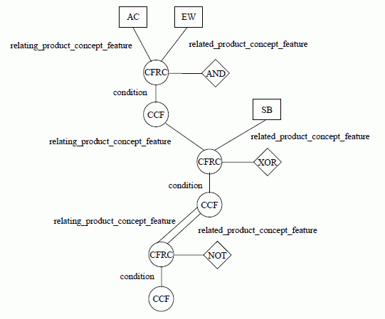
Figure E.14 shows a method of representing a similar condition in which the additional constraint is that the stronger battery is included in the car if both the air conditioning system and electric windows are present. This method uses the binary operators AND, XOR, and NOT. The boolean expression would be "NOT ((AC AND EW) XOR SB)". A concept_feature_relationship_with_condition, with a concept_feature_operator having the name "AND", establishes the relationship that both the air conditioning system and electric windows are requested. This relationship is the condition for a conditional_concept_feature that is related to the stronger battery with an XOR operator to say that either the air conditioning system and electric windows are present or the stronger battery is present. The resulting conditional_concept_feature is related with itself, by convention, to establish the condition of negation to establish the required combination of features.
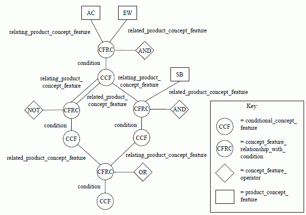
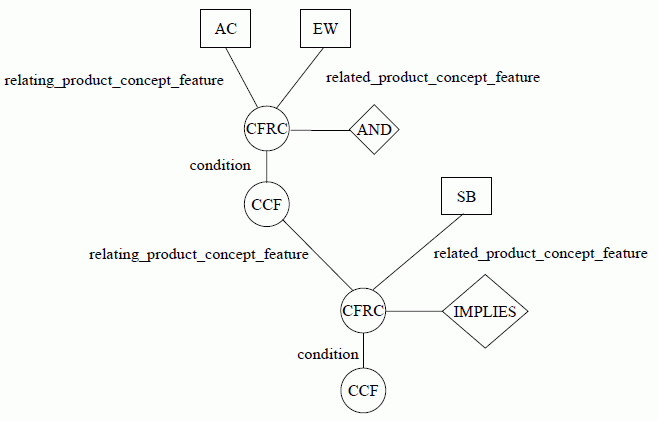
Figure E.15 shows a method of representing the same condition using the binary operator AND and by introducing an operator for implication. The expression would be "(AC AND EW) IMPLIES SB". A concept_feature_relationship_with_condition, with a concept_feature_operator having the name "AND", establishes the relationship that both the air conditioning system and electric windows are requested. This relationship is the condition for a conditional_concept_feature that is related to the stronger battery with the newly introduced IMPLIES operator. This relationship establishes the condition that either all three features are present or both the air conditioning system and electric windows are not.
© ISO 2021 — All rights reserved