Cover page
Table of contents
Copyright
Foreword
Introduction
1 Scope
2 Normative references
3 Terms, definitions and abbreviated terms
3.1 Terms and definitions
3.2 Abbreviated terms
4 Information requirements
4.1 Required AM ARMs
4.2 ARM type definitions
4.3 ARM entity definitions
4.4 ARM function definition
5 Module interpreted model
5.1 Mapping specification
5.2 MIM EXPRESS short listing
5.2.1 MIM type definitions
5.2.2 MIM entity definition
A MIM short names
B Information object
registration
C ARM EXPRESS-G

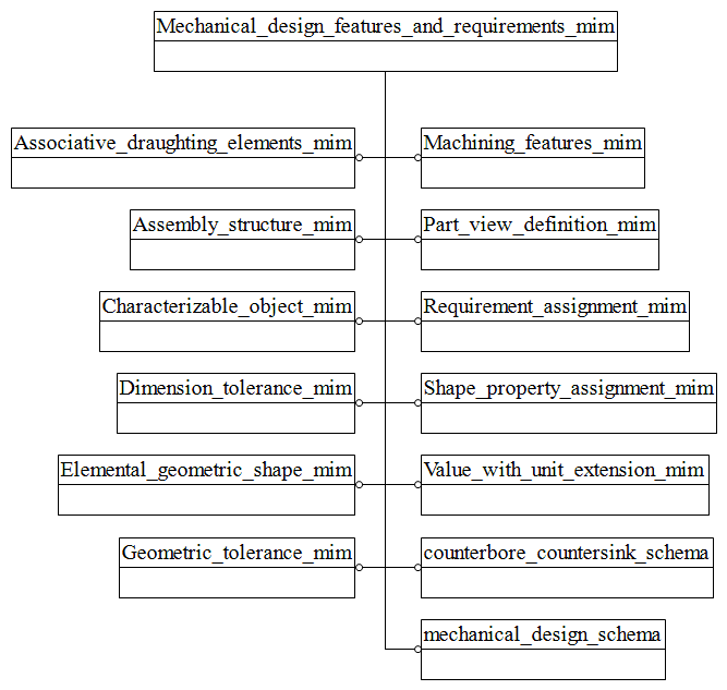
D MIM EXPRESS-G
E Computer interpretable listings
F Change history
Bibliography
Index