 As you use STEP-NC Machine
to simulate material removal, you can see
the cross section of the material being cut as well as some key
parameters calculated from that cross section. The parameters might
also be stored in the file, but the calculated ones are only available
when simulating.
As you use STEP-NC Machine
to simulate material removal, you can see
the cross section of the material being cut as well as some key
parameters calculated from that cross section. The parameters might
also be stored in the file, but the calculated ones are only available
when simulating.
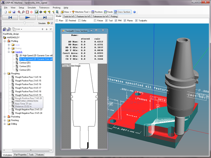
Bring up the Tool Cross Section window by clicking
the  Cross Section
button or selecting the
View | Toolpath Cross Section menu entry. The window shows the
tool coordinates, axis direction, feedrate and spindle speed of the
tool at the current toolpath location.
The cross section parameters are calculated from the material removal
simulation, but certain files may also have the parameters stored with
the toolpath. These parameters describe a 2D profile in the plane
normal to the feed direction.
Cross Section
button or selecting the
View | Toolpath Cross Section menu entry. The window shows the
tool coordinates, axis direction, feedrate and spindle speed of the
tool at the current toolpath location.
The cross section parameters are calculated from the material removal
simulation, but certain files may also have the parameters stored with
the toolpath. These parameters describe a 2D profile in the plane
normal to the feed direction.
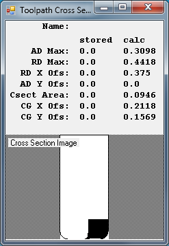
AD Max is the maximum axial depth and RD Max is the maximum radial depth of the tool contact cross section. The axial depth is measured parallel to the tool axis while the radial depth is perpendicular to both tool axis and feed direction.
RD X Ofs is the radial offset and AD Y Ofs is the axial offset of the origin (lower left corner) of tool contact cross section. These offsets are measured from the tool tip.
Csect Area is the total cross section area of the tool engagement. CG X Ofs and CG Y Ofs are the radial and axial offset of the center of gravity of this cross section area. They are also measured from the tool tip.