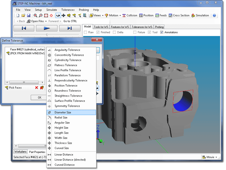
Using STEP-NC Machine you can identify geometric tolerances and dimensions (GD&T) associated with faces on your workpiece geometry. Geometric tolerances can be linked to datums that you have previously created.
Begin by selecting Tolerances | Define Tolerance ... from the application menu. This will bring up the Define Tolerance dialog, then you can select the type of geometric tolerance or dimension you would like to create from the drop-down menu. The menu is origanized into three groups: geometric tolerances, size dimensions, and distance dimensions.

The dialog will have one or two lists containing faces you have
selected for the tolerance. Add a face to the list by clicking on the
face in the geometry window. Remove a face from the list with the
 Remove button, or
clear the entire list with the
  Remove All button.
You can move the model by using the toolbar buttons on the
side of the dialog to switch the geometry window into
  Rotate, or
  Pan modes. Click on the
  Pick Face button to go back to picking faces.

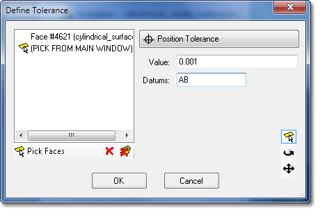
When creating geometric tolerances, such as the position tolerance shown to the left, the dialog has a list of faces, as well as a text box for the tolerance value. If the tolerance can reference datums, there will be a text box where you can type in the name of the previously created datums.
The dialog layout for size dimensions is similar, but have entry fields for plus/minus quantities as well as the nominal value.
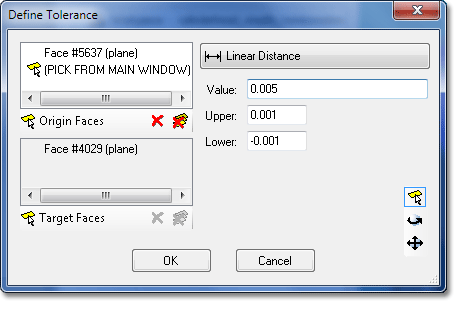
 When creating
a distance dimension, such as the linear distance shown to the
left, the dialog has two lists of faces, and you can switch
between them by clicking on the
  Origin Faces or
  Target Faces buttons.
In addition to the lists of faces, the dialog has entry fields for the nominal distance value as well as plus/minus quantities.
When you have selected the faces, values, and modifiers, click OK on the dialog to create the tolerance. You can see the tolerances, datums, and surface textures for all workpieces on the Part Properties tab.