Description
The DXF tools provide a bidirectional format conversion between the Drawing Exchange Format (DXF) and an EXPRESS schema that captures all of the data in the DXF spec. The dxf2step and step2dxf tools move data between DXF file and a P21 file based on this schema. The tools support AutoCAD Release 11 ASCII DXF format. For more information on this format, refer to the AutoCAD Release 11 Reference Manual, Appendix C.
Command Line
dxf2step [options] filename
step2dxf [options] filename
Both of these forms are wrappers that invoke the dxf_cvt executable.
- -o <filename>
- If this option is used, the output file is written with this name and the appropriate extension. Otherwise the input filename is used with the proper extension. The tool retains only that part of a filename given to it up to, but not including the first `.' It then appends the proper extension when creating the output file.
- -v
- Verbose mode, each group's code and data will be printed. Since DXF files can be thousands of lines long, this may produce a large amount of data. For a translation from STEP back to DXF, verbose mode reports every entity, table, or header item that is written.
When converting from DXF to STEP, the tool issues a running count of lines translated, warning and error messages, and a final count of the number of header section items, tables, entities, and blocks translated. When converting from STEP to DXF, the tool reports as it begins to write each section of the file and then how many items it wrote in each section. For more detailed reporting in either mode, use the -v option.
The translator will translate all groups supported by AutoCAD Release 11. Optional groups which are not present in the DXF file are assigned their default values in the STEP file. These groups are not written when converting back to DXF if they are set to the default.
Extended Entity Data is supported for every entity. If these groups are present, they are placed, in order, into a list attached to the entity in the extendHook attribute. The group code and the data are preserved. No attempt is made to decode the data.
Comments (group code 999) are reported but not saved. There is no way to maintain their context in the STEP database.
The P21 file read and written by the tools use an EXPRESS information model from STEP Tools, Inc. The EXPRESS source file for this can be found in $ROSE/docs/dxf/dxf.exp. There are also a few sample data files in this directory.
Windows Control Panel
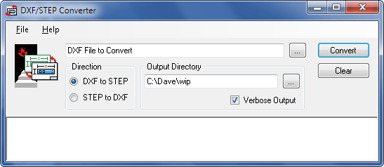
The DXF/STEP Converter Windows control panel is shown below. Run this by selecting DXF/STEP Converter from the Start Menu. The following sections describe the fields and setting on this control panel.

At the top of the DXF/STEP Converter control panel is a text field for the STEP or DXF files that you would like to check. You can open the file dialog using Ctrl+O or the [...] button to the right. You can also drag and drop files from the Windows Explorer. The Direction button should change to the appropriate value based on the file extension, but you can change it manually if needed. Click the Convert button to start.
The Output directory field indicates where the converted file should be placed. If no value is specified, the converted file will be placed in the same directory as the original file.
If Verbose output is selected, or the -v flag is given, the tool produces a detailed report of its operation.
Notes
Some assumptions needed to be made during the development of the converter. These assumptions are listed below:
- VERTEX and ATTRIB entities -- In general, these should only follow POLYLINE and INSERT entities, respectively. However, it isn't specified whether they may stand alone or not. Currently the tool supports them as free-standing entities, if they should occur, by not attaching them to a POLYLINE or INSERT entity.
- Undocumented Group Codes -- The groups for the DIMENSION table numbered 145 and up are undocumented (ref. chart on page 530 of AutoCAD Release 11 Reference Manual). Currently they represent the types that the codes 100 less represent.
- Optional Groups -- Those groups listed as optional are either assigned their default values, or, in the case of a pointer, left pointing to NULL, unless explicitly set by the input file. For Mode 2 translations, the groups are not written if they are set to their default or NULL. This can result in output files being a different size than those originally read in, i.e. if the original CAD program chose to include optional groups which were default.
- Precision -- Floating point values are now set to write to 8 places. Occasional precision errors occur in the conversion process, as the input usually contains varying field widths. The errors are primarily in the eighth decimal place.