|
|
Application module:
Schematic element |
ISO/TS 10303-1205:2005(E)
© ISO
|
This clause specifies the information requirements for the
Schematic element
application module. The information requirements are specified as the
Application Reference Model (ARM) of this application module.
NOTE 1 A graphical representation of the information
requirements is given in
Annex C.
NOTE 2 The mapping specification is specified in
5.1. It shows how
the information requirements are met by using common resources and
constructs defined or imported in the MIM schema of this application
module.
The following EXPRESS specification begins the
Schematic_element_arm
schema and identifies the necessary external references.
EXPRESS specification:
         *)

            SCHEMA Schematic_element_arm;
(*
The following EXPRESS interface statements specify the elements
imported from the ARMs of other application modules.
EXPRESS specification:
*)

            USE FROM
            Class_arm;
               --
            ISO/TS 10303-1070
            USE FROM
            Set_theory_arm;
               --
            ISO/TS 10303-1210
            USE FROM
            Draughting_annotation_arm;
               --
            ISO/TS 10303-1206
            USE FROM
            Foundation_representation_arm;
               --
            ISO/TS 10303-1006
(*
NOTE 1
The schemas referenced above are specified in the following
part of ISO 10303:
| Class_arm |
ISO/TS 10303-1070 |
| Set_theory_arm |
ISO/TS 10303-1210 |
| Draughting_annotation_arm |
ISO/TS 10303-1206 |
| Foundation_representation_arm |
ISO/TS 10303-1006 |
NOTE 2
See Annex C,
Figures
C.1and C.2
for a graphical representation of this schema.
This subclause specifies the ARM entities for this
module. Each ARM application entity is an atomic element that
embodies a unique application concept and contains attributes
specifying the data elements of the entity. The ARM
entities and definitions are specified below.
A Composition_of_schematic_element_occurrence is a relationship
between two instances of Schematic_element_occurrence (whole and part)
that indicates the part is a part of the whole.
NOTE
A composite Schematic_element_occurrence can be
a drawing layer.
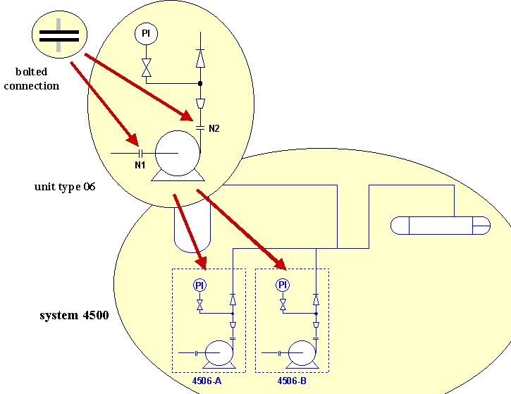
EXAMPLE 1
In Figure 1, the specification of the annotation
that stands for the bolted connection '4506-A-N1' (i.e. the bolted connection
'N1' within unit '4506-A' is a Schematic_element_occurrence. The
specification of the annotation that stands for '4506-A' is a
Schematic_element_occurrence.
The relationship between:
- the '4506-A-N1' annotation, which is a part; and
- the '4506-A' annotation, which is a whole,
is a Composition_of_schematic_element_occurrence.
EXAMPLE 2
In Figure 1, the specification of the annotations
that stands for units '4506-A' and '4506-B' are two instances of
Schematic_element_occurrence. The specification of the set of annotation
that stands for the '4506-input_system', which consists of both units, is also
a Schematic_element_occurrence.
The relationship between:
- the '4506-A' annotation, which is a part, and
- the '4506-input system' annotation, which is a whole,
is a Composition_of_schematic_element_occurrence.
Figure 1 — Schematic element definition and occurrence
EXPRESS specification:
            *)

            ENTITY Composition_of_schematic_element_occurrence;


              part : Schematic_element_occurrence;


              whole : Schematic_element_occurrence;

            END_ENTITY;
(*
Attribute definitions:
part:
a
Schematic_element_occurrence that is a part of the whole.
whole:
a
Schematic_element_occurrence that contains the part.
A Connection_of_schematic_element_occurrence is a relationship
between two instances of Schematic_element_occurrence that indicates one
is connected to the other.
A connection of schematic elements means that the juxtaposition of the two
schematic elements on the schematic drawing is intended to indicate that the
things symbolized by the schematic elements are connected.
NOTE 1
An application program may deduce the existence of connections between the
things symbolized by schematic elements, such as products or activities, from the existence of connections
between schematic elements. However, the operation of such a program is not
defined by this part of ISO 10303.
NOTE 2
An application program may maintain connections between
schematic elements by 'rubber banding' of some schematic elements, when drag
operations are carried out upon other schematic elements. However, the
operation of such a program is not defined by this part of ISO 10303.
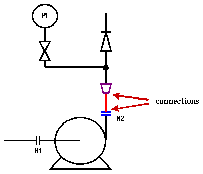
EXAMPLE 1
In Figure 2, the bolted connection N1 is symbolized
by the Schematic_element_occurrence that is two parallel lines (shown in
blue). The pipe that runs from the bolted connection to the reducer is a
Schematic_element_occurrence that is a single line (shown in red).
The relationship between:
- relationship between the bolted connection symbol; and
- the pipe symbol;
that indicates one symbol is connected to the other, is a
Connection_of_schematic_element_occurrence.
EXAMPLE 2
In Figure 2, the reducer is symbolized by the
Schematic_element_occurrence that is trapezium of lines (shown in
purple). The pipe that runs from the bolted connection to the reducer is a
Schematic_element_occurrence that is a single line (shown in red).
The relationship between:
- relationship between the reducer symbol; and
- the pipe symbol;
that indicates one symbol is connected to the other, is a
Connection_of_schematic_element_occurrence.
Figure 2 — Schematic element connection
EXPRESS specification:
            *)

            ENTITY Connection_of_schematic_element_occurrence;


              side_1 : Schematic_element_occurrence;


              side_2 : Schematic_element_occurrence;

            END_ENTITY;
(*
Attribute definitions:
side_1:
a
Schematic_element_occurrence that is connected to side_2.
side_2:
a
Schematic_element_occurrence that is connected to side_1.
A Definition_of_schematic_element_occurrence indicates that a
Schematic_element_occurrence is a subset of a Schematic_element.
The subset relationship indicates the nature of the
Schematic_element_occurrence.
EXAMPLE 1
In Figure 1, the specification of the annotation
that stands for a bolted connection is a Schematic_element_definition.
The specification of the annotation that stands for bolted connection '06-N1'
within 'unit type 06' is a Schematic_element_occurrence.
The relationship between:
- the bolted connection annotation, which is a superset; and
- the bolted connection '06-N1' annotation, which is a subset,
is a Definition_of_schematic_element_occurrence.
EXAMPLE 2
In Figure 1, the specification of the annotation
that stands for 'unit type 06' is a Schematic_element_definition. The
specification of the annotation that stands for unit '4506-A' within 'system
4500' is a Schematic_element_occurrence.
The relationship between:
- the 'unit type 06' annotation, which is a superset; and
- the '4506-A' annotation, which is a subset,
is a Definition_of_schematic_element_occurrence.
EXAMPLE 3
In Figure 1, the specification of the annotation
that stands for bolted connection '06-N1' within 'unit type 06' is a
Schematic_element_occurrence. The specification of the annotation that
stands for bolted connection '4506-A-N1' (i.e. the bolted connection 'N1'
within unit '4506-A' is a Schematic_element_occurrence
The relationship between:
- the bolted connection '06-N1' annotation, which is a superset; and
- the bolted connection '4506-A-N1' annotation, which is a subset,
is a Definition_of_schematic_element_occurrence.
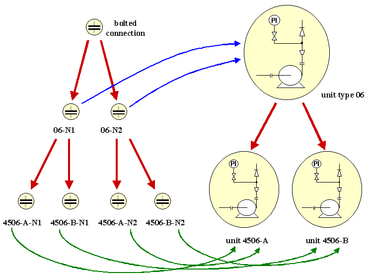
EXAMPLE 4
The Definition_of_schematic_element_occurrence
relationships illustrated in the previous examples form the tree structure shown
in Figure 3.
In this figure, the red arrow denote instances of
Definition_of_schematic_element_occurrence; the blue arrows denote
instances of Usage_of_schematic_element_occurrence;
and the green arrows denote instances of Composition_of_schematic_element_occurrence.
Figure 3 — Schematic element definition tree
EXPRESS specification:
            *)

            ENTITY Definition_of_schematic_element_occurrence

              SUBTYPE OF (Subset);


              SELF\Subset.subset : Schematic_element_occurrence;


              SELF\Subset.superset : Schematic_element_definition;

            END_ENTITY;
(*
Attribute definitions:
subset:
a
Schematic_element_occurrence that is defined by the superset.
superset:
a
Schematic_element_definition that defines the subset.
A Derivation_of_schematic_element_definition is a relationship
between two instances of Schematic_element_definition (base and
derived), that indicates the derived is obtained from the base by a geometric
transformation.
EXPRESS specification:
            *)

            ENTITY Derivation_of_schematic_element_definition;


              base : Schematic_element_definition;


              derived : Implicit_schematic_element_definition;

            END_ENTITY;
(*
Attribute definitions:
base:
a
Schematic_element_definition that is input to the geometric transformation to give the derived.
derived:
a
Implicit_schematic_element_definition that is obtained from the base by the geometric transformation.
An Explicit_schematic_element_definition is a
Schematic_element_definition that is defined by direct reference to a
detailed specification of the patches of colour, shading or texture.
EXPRESS specification:
            *)

            ENTITY Explicit_schematic_element_definition

              SUBTYPE OF (Schematic_element_definition);


              explicit_parts : SET[1:?] OF Draughting_annotation_occurrence;

            END_ENTITY;
(*
Attribute definitions:
explicit_parts:
the instances of
Draughting_annotation_occurrence that are the Schematic_element_definition.
An Implicit_schematic_element_definition is a
Schematic_element_definition that is:
- identified so that it can be obtained from an external schematic element library;
- defined as an assembly of one or more instances of
Schematic_element_occurrence; or
- defined by derivation from another Schematic_element_definition by a
geometric transformation.
For an assembled Implicit_schematic_element_definition, each
component Schematic_element_occurrence is referenced and placed within
the whole by an instance of Usage_of_schematic_element_occurrence.
For a derived Implicit_schematic_element_definition, the base
Schematic_element_definition is referenced by an instance of Derivation_of_schematic_element_definition.
EXPRESS specification:
            *)

            ENTITY Implicit_schematic_element_definition

              SUBTYPE OF (Schematic_element_definition);

            END_ENTITY;
(*
A Schematic_element is a specification for a planar two dimensional
surface of colour, shading or texture with a neglectible thickness in the third
dimension. A Schematic_element can be associated with the thing that is
stands for.
A Schematic_element is a class which has individual realisations as
ink on paper or as glowing pixels on a screen as members.
NOTE
A schematic element can be specified by:
- the closed bounding curves for the surface of colour, shading or texture;
- a centre line curve, with a width and line style;
- a location and a point symbol type; or
- a text string, with a location, orientation and font.
An schematic element can also be an assembly of schematic elements of
different types.
EXAMPLE 1
The P&ID for the cooling water system of Much
Binding B is a single schematic element.
This schematic element is an assembly of other schematic elements.
EXAMPLE 2
A electrical schematic layer for Much Binding B is a
single schematic element.
This layer can be superimposed on the Much Binding B plot plan (another
schematic element), and viewed in combination with it.
EXPRESS specification:
            *)

            ENTITY Schematic_element

              ABSTRACT SUPERTYPE

            OF (ONEOF (Schematic_element_definition,
                                Schematic_element_occurrence))

              SUBTYPE OF (Class, Representation);

            END_ENTITY;
(*
A Schematic_element_definition is a Schematic_element that is
defined solely by what it is, and not by a particular usage within another
Schematic_element.
A usage of a Schematic_element_definition is a
Schematic_element_occurrence, which has a subset relationship with the
Schematic_element_definition.
EXAMPLE 1
In Figure 1, the specification of the annotation
that stands for a bolted connection is a Schematic_element_definition.
The specification of the annotation that stands for the suction side bolted
connection 'N1' within a 'unit type 06' is a
Schematic_element_occurrence.
EXAMPLE 2
In Figure 1, the specification of the annotation
that stands for a 'unit type 06' is a Schematic_element_definition. The
specification of the annotation that stands for the unit '4506-A' within
'system 4500' is a Schematic_element_occurrence.
EXPRESS specification:
            *)

            ENTITY Schematic_element_definition

              ABSTRACT SUPERTYPE

            OF (ONEOF (Explicit_schematic_element_definition,
                                Implicit_schematic_element_definition))

              SUBTYPE OF (Schematic_element);

            END_ENTITY;
(*
A Schematic_element_occurence is a Schematic_element that is
defined by a particular usage within another Schematic_element.
A Schematic_element_occurrence is a usage of a
Schematic_element_definition, with which it has a subset relationship.
EXAMPLE 1
In Figure 1, the specification of the annotation
that stands for a bolted connection is a Schematic_element_definition.
The specification of the annotation that stands for the suction side bolted
connection 'N1' within a 'unit type 06' is a
Schematic_element_occurrence.
EXAMPLE 2
In Figure 1, the specification of the annotation
that stands for a 'unit type 06' is a Schematic_element_definition. The
specification of the annotation that stands for the unit '4506-A' within
'system 4500' is a Schematic_element_occurrence.
EXPRESS specification:
            *)

            ENTITY Schematic_element_occurrence

              SUBTYPE OF (Schematic_element);

            END_ENTITY;
(*
A Usage_of_schematic_element_occurrence is a relationship between:
- a Schematic_element_definition that is the whole; and
- a Schematic_element_occurrence that is the part.
that specifies the position and orientation of the part with respect to the
whole.
EXAMPLE 1
In Figure 1, the specification of the annotation
that stands for the suction side bolted connection '06-N1' within a 'unit type
06' is a Schematic_element_occurrence. The specification of the
annotation that stands for a 'unit type 06' is a
Schematic_element_definition.
The relationship between:
- the bolted connection '06-N1' annotation, which is a part; and
- the 'unit type 06' annotation, which is a whole,
is a Usage_of_schematic_element_occurrence.
EXAMPLE 2
In Figure 1, the specification of the annotation
that stands for the unit '4506-A' is a Schematic_element_occurrence. The
specification of the annotation that stands for a 'system 4500' is a
Schematic_element_definition.
The relationship between:
- the '4506-A' annotation, which is a part; and
- the 'system 4500' annotation, which is a whole,
is a Usage_of_schematic_element_occurrence.
EXPRESS specification:
            *)

            ENTITY Usage_of_schematic_element_occurrence;


              part : Schematic_element_occurrence;


              whole : Implicit_schematic_element_definition;

            END_ENTITY;
(*
Attribute definitions:
part:
a
Schematic_element_occurrence that has a particular position and orientation within the whole.
whole:
an
Implicit_schematic_element_definition that contains the part.
         *)

         END_SCHEMA;  -- Schematic_element_arm
(*
© ISO 2005 — All rights reserved


