|
|
Application module:
Additive manufacturing part and build information |
ISO/TS 10303-1835:2019(E)
© ISO
|
This clause specifies the information requirements for the
Additive manufacturing part and build information
application module. The information requirements are specified as the
Application Reference Model (ARM) of this application module.
NOTE 1 A graphical representation of the information
requirements is given in
Annex C.
NOTE 2 The mapping specification is specified in
5.1. It shows how
the information requirements are met by using common resources and
constructs defined or imported in the MIM schema of this application
module.
This clause defines the information requirements to which implementations shall
conform using the EXPRESS language as defined in ISO 10303-11.
The following begins the
Additive_manufacturing_part_and_build_information_arm
schema and identifies the necessary external references.
EXPRESS specification:
         *)

            SCHEMA Additive_manufacturing_part_and_build_information_arm;
(*
The following EXPRESS interface statements specify the elements
imported from the ARMs of other application modules.
EXPRESS specification:
*)

            USE FROM
            Assembly_structure_arm;
               --
            ISO/TS 10303-1026
            USE FROM
            Construction_geometry_arm;
               --
            ISO/TS 10303-1131
            USE FROM
            Elemental_geometric_shape_arm;
               --
            ISO/TS 10303-1004
            USE FROM
            Item_definition_structure_arm;
               --
            ISO/TS 10303-1345
            USE FROM
            Part_shape_arm;
               --
            ISO/TS 10303-1807
            USE FROM
            Part_view_definition_arm;
               --
            ISO/TS 10303-1023
            USE FROM
            Process_plan_arm;
               --
            ISO/TS 10303-1803
            USE FROM
            Value_with_unit_extension_arm;
               --
            ISO/TS 10303-1753
(*
NOTE 1
The schemas referenced above are specified in the following
part of ISO 10303:
| Assembly_structure_arm |
ISO/TS 10303-1026 |
| Construction_geometry_arm |
ISO/TS 10303-1131 |
| Elemental_geometric_shape_arm |
ISO/TS 10303-1004 |
| Item_definition_structure_arm |
ISO/TS 10303-1345 |
| Part_shape_arm |
ISO/TS 10303-1807 |
| Part_view_definition_arm |
ISO/TS 10303-1023 |
| Process_plan_arm |
ISO/TS 10303-1803 |
| Value_with_unit_extension_arm |
ISO/TS 10303-1753 |
NOTE 2
See Annex C,
Figures
C.1, C.2, C.3and C.4
for a graphical representation of this schema.
This subclause specifies the ARM type
for this application module. The ARM type and
definition is specified below.
An ampubi_initial_application_domain_enumeration provides predefined identifiers for the initial application domains of
Product_view_definitions.
EXPRESS specification:
            *)

            TYPE
            ampubi_initial_application_domain_enumeration =

            ENUMERATION

            BASED_ON
            initial_application_domain_enumeration
            WITH


            (additive_manufacturing);

            END_TYPE;

            (*
Enumerated item definitions:
additive_manufacturing:
the application domain is additive_manufacturing.
This subclause specifies the ARM entities for this
module. Each ARM application entity is an atomic element that
embodies a unique application concept and contains attributes
specifying the data elements of the entity. The ARM
entities and definitions are specified below.
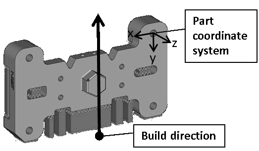
An Additive_manufacturing_build_direction_element is a type of
Additive_manufacturing_orientation_element that defines the build orientation for processes employing planar layer addition of material.
Figure 1 — An illustration of the build direction
EXPRESS specification:
            *)

            ENTITY Additive_manufacturing_build_direction_element

              SUBTYPE OF (Additive_manufacturing_orientation_element);
WHERE

              WR1: EXISTS(SELF\Shape_element.identified_item.axis);

            END_ENTITY;
(*
Formal propositions:
WR1:
the attribute identified_item inherited from the Additive_manufacturing_orientation_element shall have an Axis_placement_3d.axis defined.
An Additive_manufacturing_orientation_element is a type of
Part_shape_element that defines the initial build orientation of a part when an Additive_manufacturing_setup is not yet defined. For an additive manufacturing process, the initial build orientation is defined in ISO/ASTM 52921.
EXPRESS specification:
            *)

            ENTITY Additive_manufacturing_orientation_element

              ABSTRACT SUPERTYPE


              SUBTYPE OF (Part_shape_element);


              SELF\Shape_element.associated_definition : Additive_manufacturing_part_definition;


              SELF\Shape_element.identified_item : Axis_placement_3d;
DERIVE

              SELF\Shape_element.element_name : STRING := 'additive manufacturing build orientation';

            END_ENTITY;
(*
Attribute definitions:
associated_definition:
an attribute inherited from the Part_shape_element that defines the Additive_manufacturing_part_definition.
identified_item:
an attribute inherited from the Part_shape_element that specifies the axes of the initial build orientation.
element_name:
an attribute inherited from the Part_shape_element that specifies the element name as 'additive manufacturing build orientation'.
An Additive_manufacturing_part_definition is a type of
Part_view_definition that defines a part to be manufactured by an additive manufacturing process.
EXPRESS specification:
            *)

            ENTITY Additive_manufacturing_part_definition

              SUBTYPE OF (Part_view_definition);
INVERSE

              design_relationship : Geometrical_relationship FOR relating_view;
WHERE

              WR1: SELF\Product_view_definition.initial_context\Initial_view_definition_context.application_domain = ampubi_initial_application_domain_enumeration.additive_manufacturing;

            END_ENTITY;
(*
Attribute definitions:
design_relationship:
specifies the design part view definition.
Formal propositions:
WR1:
the initial application domain shall be additive_manufacturing.
An Additive_manufacturing_setup is a type of
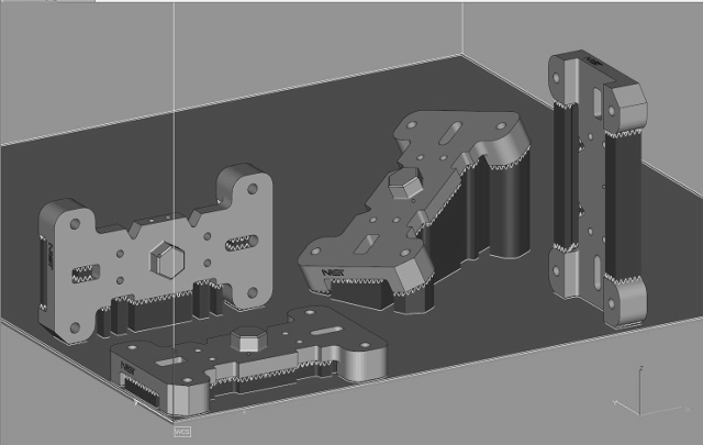
Assembly_definition that defines the setup for one or more workpieces, the support structures and the build plate. The coordinate system of
the build plate shall be the same as the coordinate system of Additive_manufacturing_setup.
Figure 2 — Illustration of a setup with 4 occurrences of the part and its support structures
EXPRESS specification:
            *)

            ENTITY Additive_manufacturing_setup

              SUBTYPE OF (Assembly_definition);


              its_origin : Axis_placement_3d;
INVERSE

              its_workpiece_setup : SET[1:?] OF Additive_manufacturing_workpiece_setup FOR relating_view;

              its_support_setup : SET[0:?] OF Additive_manufacturing_support_structure_setup FOR relating_view;

              its_build_plate_setup : Additive_manufacturing_setup_build_plate FOR relating_view;

            END_ENTITY;
(*
Attribute definitions:
its_origin:
specifies the frame of reference for the location of each workpiece in a setup.
its_workpiece_setup:
specifies one or more workpieces to be manufactured.
its_support_setup:
specifies the support structures of the workpieces.
its_build_plate_setup:
specifies the build plate.
An Additive_manufacturing_setup_build_plate is a type of
Next_assembly_usage that specifies the usage of a build plate in the setup.
EXPRESS specification:
            *)

            ENTITY Additive_manufacturing_setup_build_plate

              SUBTYPE OF (Next_assembly_usage);


              SELF\Product_occurrence_definition_relationship.related_view RENAMED its_build_plate : Build_platform_definition;


              SELF\Product_occurrence_definition_relationship.relating_view : Additive_manufacturing_setup;
INVERSE

              placement : Contextual_shape_representation FOR product_context;

            END_ENTITY;
(*
Attribute definitions:
its_build_plate:
an attribute inherited from the Product_occurrence_definition_relationship that defines the build platform.
relating_view:
an attribute inherited from the Product_occurrence_definition_relationship that defines the setup.
placement:
specifies the transformation allowing the placement of the build platform in the setup.
An Additive_manufacturing_support_structure is a type of
Part_view_definition that defines the optional support structures of the parts specified in the setup.
EXPRESS specification:
            *)

            ENTITY Additive_manufacturing_support_structure

              SUBTYPE OF (Part_view_definition);
WHERE

              WR1: SELF\Product_view_definition.initial_context\Initial_view_definition_context.application_domain = ampubi_initial_application_domain_enumeration.additive_manufacturing;

            END_ENTITY;
(*
Formal propositions:
WR1:
the initial application domain shall be additive_manufacturing.
An Additive_manufacturing_support_structure_setup is a type of
Next_assembly_usage that specifies the usage of support structures in the setup.
EXPRESS specification:
            *)

            ENTITY Additive_manufacturing_support_structure_setup

              SUBTYPE OF (Next_assembly_usage);


              SELF\Product_occurrence_definition_relationship.related_view RENAMED its_support : Additive_manufacturing_support_structure;


              SELF\Product_occurrence_definition_relationship.relating_view : Additive_manufacturing_setup;
INVERSE

              placement : Contextual_shape_representation FOR product_context;

            END_ENTITY;
(*
Attribute definitions:
its_support:
an attribute inherited from the Product_occurrence_definition_relationship that define the support structures.
relating_view:
an attribute inherited from the Product_occurrence_definition_relationship that define the setup.
placement:
specifies the transformation allowing the placement of the support structures in the setup.
An Additive_manufacturing_workpiece_setup is a type of
Next_assembly_usage that specifies the usage of a workpiece in the setup. If the build direction of the Additive_manufacturing_part_definition is defined, the placement shall ensure that the build direction is in the z direction of the build platform. If the reference direction of the Additive_manufacturing_part_definition is defined, the placement shall ensure that the x direction is in the x direction of the build platform.
EXPRESS specification:
            *)

            ENTITY Additive_manufacturing_workpiece_setup

              SUBTYPE OF (Next_assembly_usage);


              SELF\Product_occurrence_definition_relationship.related_view RENAMED its_workpiece : Additive_manufacturing_part_definition;


              SELF\Product_occurrence_definition_relationship.relating_view : Additive_manufacturing_setup;
INVERSE

              placement : Contextual_shape_representation FOR product_context;

            END_ENTITY;
(*
Attribute definitions:
its_workpiece:
an attribute inherited from the Product_occurrence_definition_relationship that defines the part that will be used as workpiece.
relating_view:
an attribute inherited from the Product_occurrence_definition_relationship that defines the setup.
placement:
specifies the transformation allowing the placement of the workpiece in the setup.
An Additive_manufacturing_workplan is a type of
Executable that defines the additive manufacturing operation.
EXPRESS specification:
            *)

            ENTITY Additive_manufacturing_workplan

              SUBTYPE OF (Executable);


              its_setup : Additive_manufacturing_setup;

            END_ENTITY;
(*
Attribute definitions:
its_setup:
defines the setup for the Additive_manufacturing_workplan.
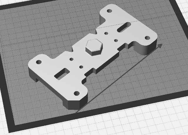
An Additive_manufacturing_x_direction_element is a type of
Additive_manufacturing_orientation_element that defines the part orientation relative to the front of the build surface.
Figure 3 — An illustration of the X direction
EXPRESS specification:
            *)

            ENTITY Additive_manufacturing_x_direction_element

              SUBTYPE OF (Additive_manufacturing_orientation_element);
WHERE

              WR1: EXISTS(SELF\Shape_element.identified_item.ref_direction);

            END_ENTITY;
(*
Formal propositions:
WR1:
the attribute identified_item inherited from the Additive_manufacturing_orientation_element shall have an Axis_placement_3d.ref_direction defined.
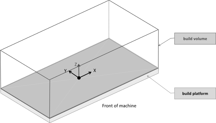
A Build_platform_definition is a type of Product_view_definition that defines a build platform. The coordinate system shall be oriented so that the plane of build platform is in the xy plane
at z value 0. And the z direction points in the direction above the build platform into the build volume.
Figure 4 — Illustration of a build platform with its build volume
EXPRESS specification:
            *)

            ENTITY Build_platform_definition

              SUBTYPE OF (Product_view_definition);


              build_volume_representation : Build_volume;


              build_platform_representation :
            OPTIONAL
            Geometric_model;

            END_ENTITY;
(*
Attribute definitions:
build_volume_representation:
defines the representation of the build volume.
build_platform_representation:
defines the geometric representation of the build platform. For an additive manufacturing process, the build platform is
defined in ISO/ASTM 52921. The value of this attribute need not be specified.
A Build_volume is a type of
Geometric_model that specifies the build volume. For an additive manufacturing process, the build volume is defined in ISO/ASTM 52921.
A Build_volume is either a Rectangular_build_volume or a Circular_build_volume.
EXPRESS specification:
            *)

            ENTITY Build_volume

              ABSTRACT SUPERTYPE

            OF (ONEOF (Rectangular_build_volume,
                                Circular_build_volume))

              SUBTYPE OF (Geometric_model);


              its_origin : Axis_placement_3d;

            END_ENTITY;
(*
Attribute definitions:
its_origin:
specifies the frame of reference for the location and the orientation of the build volume.
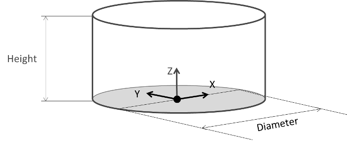
A Circular_build_volume is a type of
Build_volume that is circular. A Circular_build_volume is specified by its diameter size.
Figure 5 — Illustration of a circular build volume for an additive Manufacturing Machine/System (Upward Building)
EXPRESS specification:
            *)

            ENTITY Circular_build_volume

              SUBTYPE OF (Build_volume);


              diameter : Length_data_element;


              height :
            OPTIONAL
            Length_data_element;

            END_ENTITY;
(*
Attribute definitions:
diameter:
defines the diameter of the build platform.
height:
defines the height of the build platform. The value of this attribute need not be specified.
An Executable is a type of
Process_operation_definition that defines a manufacturing or control operation, such as a machining working step, NC function or program structure.
NOTE
The term “executable” is defined by ISO 10303-238 and is reused here for reasons of interoperability.
EXPRESS specification:
            *)

            ENTITY Executable

              SUBTYPE OF (Process_operation_definition);

            END_ENTITY;
(*
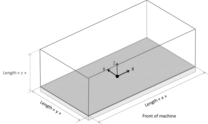
A Rectangular_build_volume is a type of Build_volume that is rectangular.
Figure 6 — Illustration of a rectangular build volume for an additive Manufacturing Machine/System (Upward Building)
EXPRESS specification:
            *)

            ENTITY Rectangular_build_volume

              SUBTYPE OF (Build_volume);


              x : Length_data_element;


              y : Length_data_element;


              z :
            OPTIONAL
            Length_data_element;

            END_ENTITY;
(*
Attribute definitions:
x:
defines the size of the build platform along the X direction.
y:
defines the size of the build platform along the Y direction.
z:
defines the size of the build platform along the Z direction. The value of this attribute need not be specified.
This subclause specifies the ARM subtype constraint for
this module. The subtype constraint places a constraint on the
possible super-type / subtype instantiations.
The ARM subtype constraint and definition is
specified below.
The
Additive_manufacturing_part_view_subtypes
constraint specifies a constraint that applies to instances of
Part_view_definition
and enforces the rule that its subtypes
Additive_manufacturing_part_definition and Additive_manufacturing_support_structure
are exclusive.
EXPRESS specification:
            *)
SUBTYPE_CONSTRAINT Additive_manufacturing_part_view_subtypes FOR Part_view_definition;

              ONEOF (Additive_manufacturing_part_definition,
         Additive_manufacturing_support_structure);

            END_SUBTYPE_CONSTRAINT;
(*
         *)

         END_SCHEMA;  -- Additive_manufacturing_part_and_build_information_arm
(*
© ISO 2019 — All rights reserved


