Make Additive Process Plan
The sample program below creates an additive manufacturing process for laser powder bed fusion of a simple part. This reads in CAD geometry, slices it and creates STEP-NC toolpaths. Afterwards, it walks through the process and generates some machine tool control codes from the toolpaths for use with a machine.
Note: these programs will run, but saving the model requires a license key from STEP Tools.
We start by creating a new project and getting the main workplan, which is where we will put our powder bed fusion plan.
#! python import sys import os from steptools import step from steptools.step import AptAPI as apt from steptools.step import ToleranceAPI as tol step.verbose(False) print (\n\n--------------------) print (TEST: create new additive plan) D = step.new_project(foo) PROJ = apt.get_current_project() print (Project:, PROJ) PLAN = apt.get_current_workplan() print (Main Plan:, PLAN)
Next we import the CAD model for the piece that we are making, create a setup transform that adjusts the working coordinate system to something more convenient, and then create the additive plan. The API will slice the part and create process according to the selected parameters.
# Read in workpiece CAD description PIECE = apt.workpiece(7AJS9999-0001A.stp) print (Workpiece:, PIECE) # if you need to move the workpiece after importing # apt.put_workpiece_placement(PIECE, x,y,z, i,j,k, a,b,c) # create a setup with placement, omit ijk, abc which default to Z and X axis apt.workplan_setup(PLAN, -2.625, 15, 4.95) # Workpieces have an enclosing assembly for repositioning. # Get first child COMPONENT = PIECE.its_components[0].component print (Component:, COMPONENT) SHAPE = COMPONENT.its_geometry print (Shape:, SHAPE) # Plan additive paths using workplan and shape rep. Below we use # coarser parameters than the default so that we go faster. # # The following keyword params and defaults are available # name = # index = -1 # pre_contour = False # post_contour = True # theta_interlayer_rotation = 69 # overlap = 0.25 # layer_thickness = 0.004 # hatch_space = 0.0085 # theta_island_rotation = 90 # rectangle_length = 1.25 # rectangle_width = 0.75 # first_layer = -1; bottom of part, default layer 0 # last_layer = -1; top of part, default max layer print (Generating Additive Plan for first ten layers) ADDPLAN = tol.plan_additive_layer( PLAN, SHAPE, name=additive, first_layer=0, last_layer=10 ) print (ADDPLAN:, ADDPLAN)
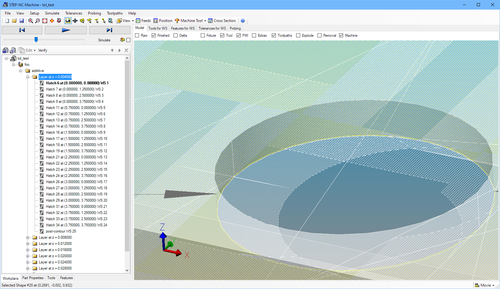
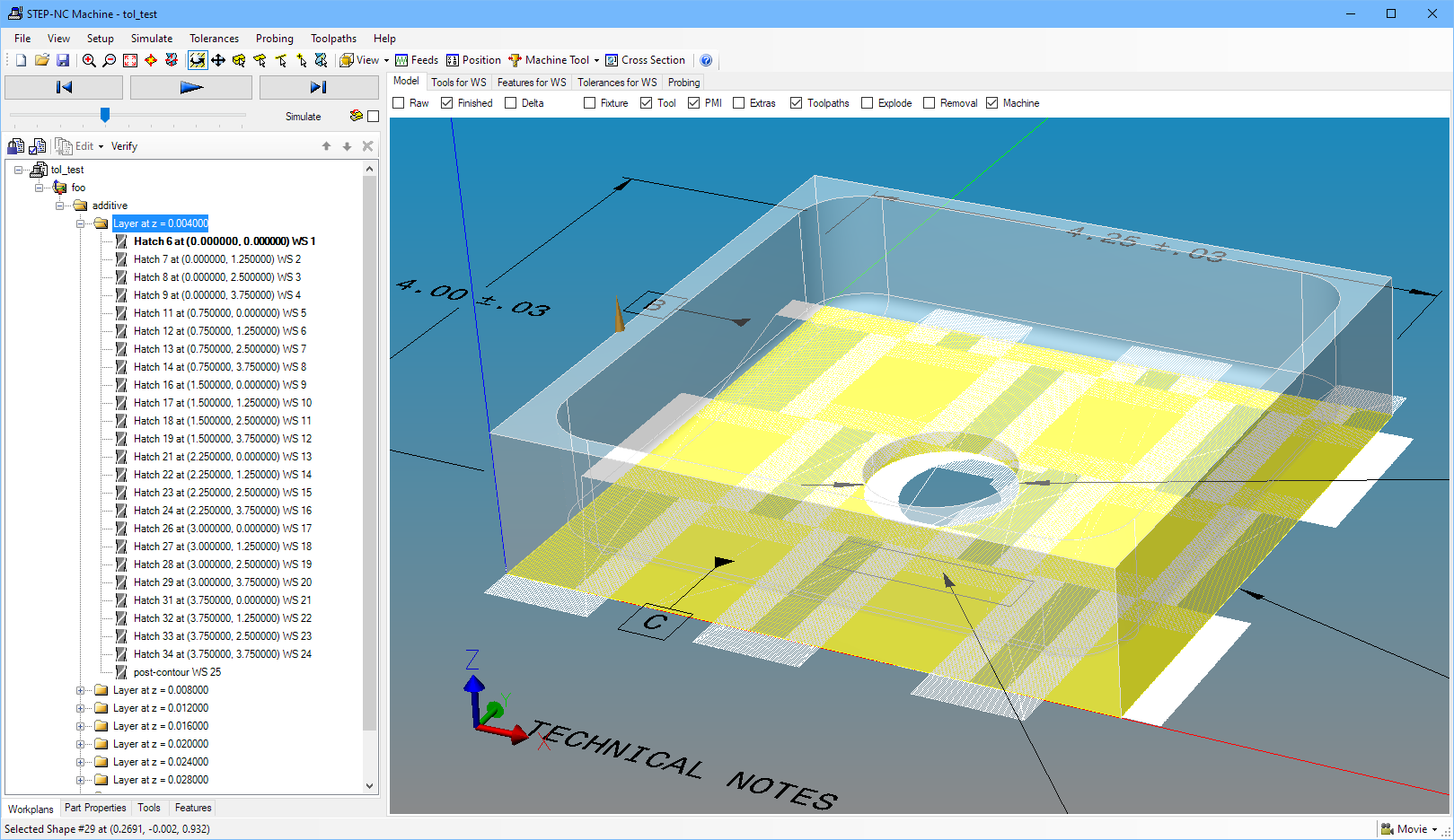
At this point, the ADDPLAN workplan contains nested workplans and workingsteps with toolpaths for each of the ten layers, one of which is pictured below. This is a large volume of toolpath data, which we can save or walk through to do something with as shown in the following code
Walking through the process, we can turn off some of the details and just print workingsteps to get an idea of what is there. Refer to our more detailed machine code generation examples to see how to adapt this to your own needs.
CUR = step.Adaptive()
GEN = step.Generate()
GS = step.GenerateState()

CUR.start_project(D)
CUR.set_wanted_all()

# Turn off toolpath details and only print workingsteps start/end for
# this sample.  Obviously, you would want all of the toolpath details
# when trying to actually use the additive paths.
CUR.set_wanted(step.CtlEvent.MOVE, False)
CUR.set_wanted(step.CtlEvent.CURVE_START, False)
CUR.set_wanted(step.CtlEvent.CURVE_END, False)
CUR.set_wanted(step.CtlEvent.TOOLPATH_START, False)
CUR.set_wanted(step.CtlEvent.TOOLPATH_END, False)

GEN.set_style(fanuc)

# print empty string when the format returns None, do not end with a
# newline since the format strings already have them where needed.
while CUR.next():
    print(GEN.format_event(GS,CUR) or '', end='')


# Can save process as STEP-NC file if desired.
# step.save("additive_test.stpnc")