Overview
The ToleranceAPI module has functions to create and manipulate tolerance data for applications such as:
- Finding the tolerances in an AP242 STEP file.
- Adding tolerances to an AP242 STEP file.
- Generating probing operations to measure points related to a tolerance value.
- Computing relationships between tolerances and tools so that tolerance errors can be compensated in the next round of machining.
There is no need to create an instance of ToleranceAPI, it is just a namespace that collects related functions in one place as class methods.
add_workpiece_hardness()
@classmethod
def add_workpiece_hardness(cls,
	workpiece: Object,
	value: float,
	measuring_method: str
	) -> Object:
The add_workpiece_hardness() function adds a hardness description to workpiece, and returns the hardness object. The value is interpreted using a measuring method.
Keyword Parameters
- workpiece: Object
- The workpiece to be described.
- value: float
- The required hardness value. This value is unitless.
- measuring_method: str
- The measuring method to be used to interpret the hardness value.
The following values are recommended.
ROCKWELL
BRINELL
VICKERS
LOEB
add_workpiece_material()
@classmethod
def add_workpiece_material(cls,
	workpiece: Object,
	material: str,
	material_standard: str
	) -> Object:
The add_workpiece_material() function adds a material description description to workpiece, and returns the material object. The standard defining the material name must be identified.
Keyword Parameters
- workpiece: Object
- The workpiece to be described.
- material: str
- The material value as defined by the standard.
- material_standard: str
- The standard that defines the meaning of the value
add_workpiece_treatment()
@classmethod
def add_workpiece_treatment(cls,
	workpiece: Object,
	treatment_type: str,
	value: str
	) -> Object:
The add_workpiece_treatment() function adds a treatment description to workpiece, then returns the treatment object. The most common kind of treatment is heat and the add_workpiece_treatment_heat() function is a convenience function for that case.
Keyword Parameters
- workpiece: Object
- The workpiece to be described.
- treatment_type: str
- The type of the treatment.
- value: str
- The value of the treatment.
add_workpiece_treatment_heat()
@classmethod
def add_workpiece_treatment_heat(cls,
	workpiece: Object,
	value: str
	) -> Object:
The add_workpiece_treatment_heat() function adds a treatment
description with a type of heat
to workpiece, and returns the
treatment object.
Keyword Parameters
- workpiece: Object
- The workpiece to be described.
- value: str
- The value of the treatment.
get_tolerance_face_all()
@classmethod
def get_tolerance_face_all(cls,
	tolerance: Object
	) -> List[Object]:
The get_tolerance_face_all() function returns a list of the faces constrained by a tolerance. For a location tolerance these will be faces in both the origin and target of the tolerance. The list may contain any type of geometric representation item connected to the tolerance, not just faces.
Keyword Parameters
- tolerance: Object
- The tolerance to query for faces.
get_tolerance_origin_face_all()
@classmethod
def get_tolerance_origin_face_all(cls,
	tolerance: Object
	) -> List[Object]:
The get_tolerance_origin_face_all() function returns a list of the faces the origin of a dimension. Location dimensions describe a distance between an origin and target. The list may contain any type of geometric representation item connected to the tolerance, not just faces.
Keyword Parameters
- tolerance: Object
- The tolerance to query for faces.
get_tolerance_target_face_all()
@classmethod
def get_tolerance_target_face_all(cls,
	tolerance: Object
	) -> List[Object]:
The get_tolerance_target_face_all() function returns a list of the faces the target of a dimension. Location dimensions describe a distance between an origin and target. The list may contain any type of geometric representation item connected to the tolerance, not just faces.
Keyword Parameters
- tolerance: Object
- The tolerance to query for faces.
plan_additive_layer()
@classmethod
def plan_additive_layer(cls,
	workplan: Object,
	shape: Object,
	index: int = -1,
	name: str = ,
	pre_contour: bool = False,
	post_contour: bool = True,
	theta_interlayer_rotation: float = 69,
	overlap: float = 0.25,
	layer_thickness: float = 0.004,
	hatch_space: float = 0.0085,
	theta_island_rotation: float = 90,
	rectangle_length: float = 1.25,
	rectangle_width: float = 0.75,
	first_layer: int = -1,
	last_layer: int = -1
	) -> Object:
The plan_additive_layer() function creates a workplan for
layered manufacturing with powder bed fusion. It will slice the
geometry given in the shape parameter and create a series
of nested workplans, one for each layer, containing the scan paths as
workingsteps. The function returns the new workplan object.
The layer parameters and subdivision into patches according to a chess strategy are controlled by the parameters. Each layer can be bounded by a contour pass before the infill moves, after them, or both.
Keyword Parameters
- workplan
- The created additive workplan will be added to this workplan
object at the location given by
index. This parameter is required and must be an instance of themachining_workplan
EXPRESS type. - shape
- The geometric shape given by this parameter will be sliced to
create the layers made by of the resulting workplan. The number of
layers will depend on the Z dimension of the shape and
the
layer_thickness. This parameter is required and must be an instance of theshape_representation
EXPRESS type. - index
- The created additive workplan will be inserted into the sequence
of steps in the
workplanobject before this location. A value of zero inserts at the start. The default value of minus one (-1) appends after the last element. - name
- An identifying name for the overall created workplan. The default
value is the empty string . The nested workplans for each layer and
hatch will have generated names like
Layer at z=0.123
andHatch 123 at (0.456, 0.789) WS 12
- pre_contour
- True if the workplan for a layer should start with a toolpath that
goes around any inner or outer perimeters of the layer before starting
any filling paths. The default value is False.
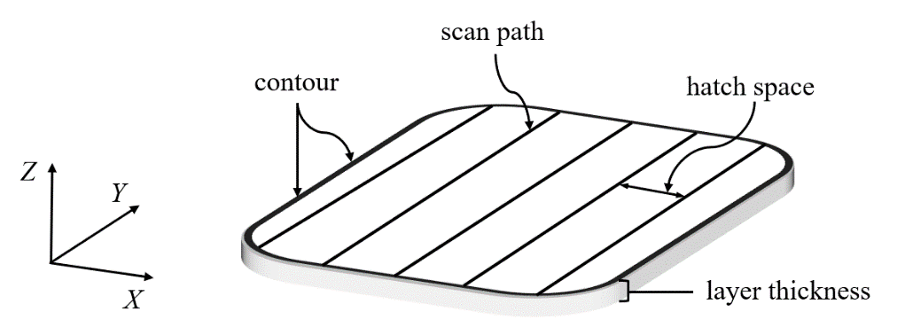
Layer Parameters - post_contour
- True if the workplan for a layer should end with a toolpath that goes around any inner or outer perimeters of the layer after completing any filling paths. The default value is True.
- theta_interlayer_rotation
- The rotation angle, in degrees, between the scan strategy of the current layer with respect to the scan strategy of the previous layer. A positive angle value indicating a counterclockwise rotation from the previous layer, a negative value a clockwise rotation. The default value is 69 degrees.
- overlap
- The distance of overshoot with power off when reversing direction. Allows mechanical systems to stop moving in one direction and accelerate to speed in the other direction before the laser power comes back on. The default value is 0.25.
- layer_thickness
- The distance between layer slices in the workplan. A smaller value produuces more layers and a larger value produces fewer. The default value is 0.004.
- hatch_space
- The distance between two consecutive scan paths when generating the back-and-forth filling paths.
- theta_island_rotation
- The rotation angle, in degrees, between adjacent the islands
produced by the chess strategy for fill paths.
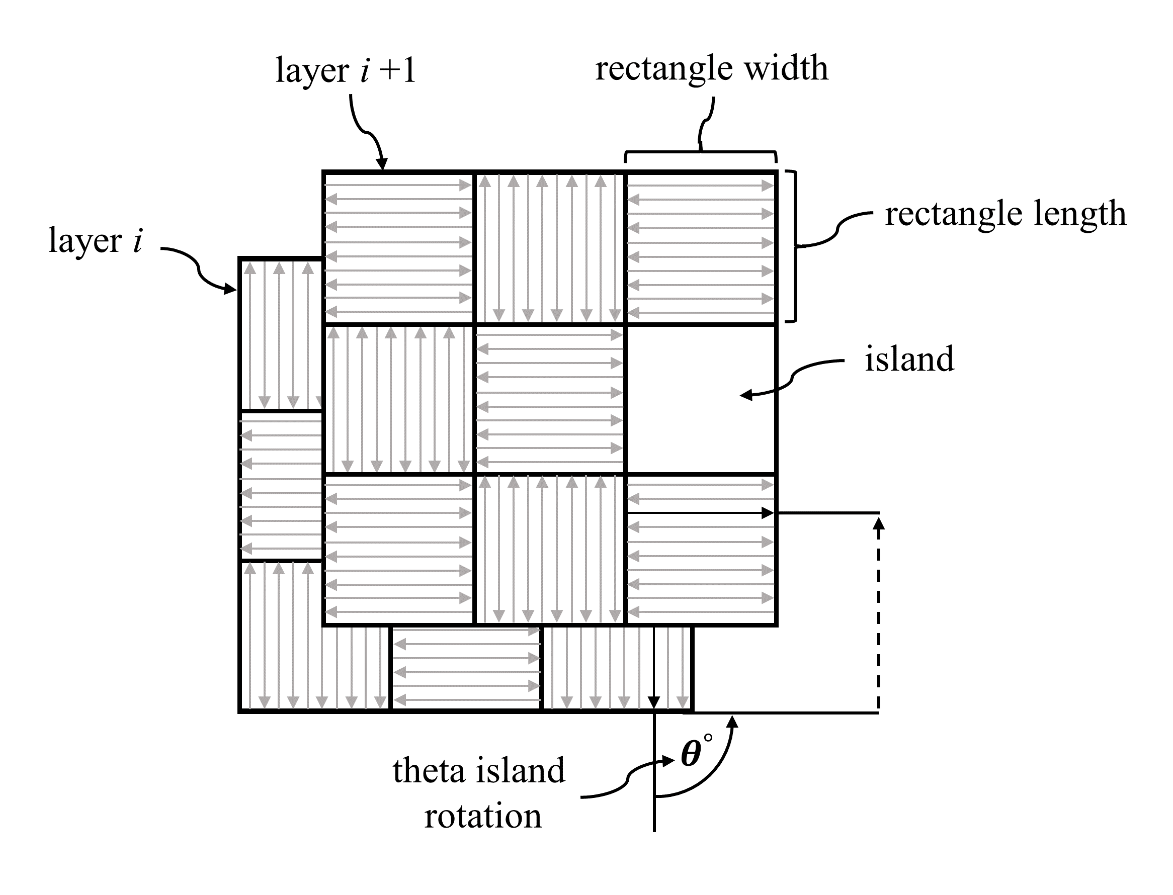
Chess Strategy Parameters - rectangle_length
- One dimension of the islands produced by the chess strategy for fill paths.
- rectangle_width
- The other dimension of the islands produced by the chess strategy for fill paths.
- first_layer
- The lowest layer to generate process for. The default value is zero, indicating the lowest Z value layer of the shape.
- last_layer
- The index of the highest layer to generate process for. The
default value is -1, indicating the highest Z value layer of the
shape. The number of layers is controlled by the Z extent of the
shape and the
layer_thicknessparameter.
plan_any_probing()
@classmethod
def plan_any_probing(cls,
	workplan: Object,
	index: int,
	name: str,
	face: Object,
	point_count: int,
	edge_tol: float
	) -> Object:
The plan_any_probing() function creates a workplan with probing workingsteps to test position and profile of any surface. The function returns the new workplan. All probing operations operate on a new feature that contains the face being probed.
The number of points generated depends on the available area on the surface. It also depends on the size of the edge tolerance because the points generated should not be within this distance of the edge. If these conditions are met then the requested count of points will be geneated, otherwise fewer points will be created.
This function selects points at random from the underlying mesh and tries to keep them well spaced. The spline, cylinder, and plane probing functions create probing points in regular grids.
Keyword Parameters
- workplan: Object
- The workplan that is to contain the new nested workplan.
- index: int
- The new workplan will be inserted into the sequence of steps in
the
workplanobject before this location. A value of zero inserts at the start. The default value of minus one (-1) appends after the last element. - name: str
- Name for the new probing workplan
- face: Object
- The face describing the surface to be probed
- point_count: int
- The desired number points.
- edge_tol: float
- A desired minimum distance from the boundary for any point chosen on the face.
plan_bspline_probing()
@classmethod
def plan_bspline_probing(cls,
	workplan: Object,
	index: int,
	name: str,
	face: Object,
 	num_u_points: int,
 	num_v_points: int
	) -> Object:
The plan_bspline_probing() function creates a workplan with probing workingsteps to test position and profile of a b-spline surface. The function returns the new workplan. All probing operations operate on a new feature that contains the face being probed.
Ideally one probe point is generated for each UV combination. For example, if U=3 and V=5 then there will be 15 points. However, any point is inside a hole or outside the boundary of the face will be omitted. If necessary the location of the u and v can be nudged using the plan_set_delta_uv() function.
Keyword Parameters
- workplan: Object
- The workplan that is to contain the new nested workplan.
- index: int
- The new workplan will be inserted into the sequence of steps in
the
workplanobject before this location. A value of zero inserts at the start. The default value of minus one (-1) appends after the last element. - name: str
- Name for the new probing workplan
- face: Object
- The face describing the surface to be probed
- num_u_points: int
- The desired number U points.
- num_v_points: int
- The desired number V points.
plan_cylinder_probing()
@classmethod
def plan_cylinder_probing(cls,
	workplan: Object,
	index: int,
	name: str,
	face: Object,
 	num_u_points: int,
 	num_v_points: int
	) -> Object:
The plan_cylinder_probing() function creates a workplan with probing workingsteps to test position and profile of a cylindrical surface. The function returns the new workplan. All probing operations operate on a new feature that contains the face being probed.
Ideally one probe point is generated for each UV combination. For example, if U=3 and V=5 then there will be 15 points. However, any point is inside a hole or outside the boundary of the face will be omitted. If necessary the location of the u and v can be nudged using the plan_set_delta_uv() function.
Keyword Parameters
- workplan: Object
- The workplan that is to contain the new nested workplan.
- index: int
- The new workplan will be inserted into the sequence of steps in
the
workplanobject before this location. A value of zero inserts at the start. The default value of minus one (-1) appends after the last element. - name: str
- Name for the new probing workplan
- face: Object
- The face describing the surface to be probed
- num_u_points: int
- The desired number U points.
- num_v_points: int
- The desired number V points.
plan_plane_probing()
@classmethod
def plan_plane_probing(cls,
	workplan: Object,
	index: int,
	name: str,
	face: Object,
 	num_u_points: int,
 	num_v_points: int
	) -> Object:
The plan_plane_probing() function creates a workplan with probing workingsteps to test position and profile of a planar surface. The function returns the new workplan. All probing operations operate on a new feature that contains the face being probed.
Ideally one probe point is generated for each UV combination. For example, if U=3 and V=5 then there will be 15 points. However, any point is inside a hole or outside the boundary of the face will be omitted. If necessary the location of the u and v can be nudged using the plan_set_delta_uv() function.
Keyword Parameters
- workplan: Object
- The workplan that is to contain the new nested workplan.
- index: int
- The new workplan will be inserted into the sequence of steps in
the
workplanobject before this location. A value of zero inserts at the start. The default value of minus one (-1) appends after the last element. - name: str
- Name for the new probing workplan
- face: Object
- The face describing the surface to be probed
- num_u_points: int
- The desired number U points.
- num_v_points: int
- The desired number V points.
plan_set_delta_uv()
@classmethod
def plan_set_delta_uv(cls,
	delta_u: float,
	delta_v: float
	) -> None:
The plan_set_delta_uv() function adjusts the starting U and V values by delta values, to nudge the grid points to a location where they may encounter less holes or fit better with the shape of the boundary
The plan probing operations use the face edge loop to compute maximum and minimum values for initial points on the face and then generating a grid of points between these maxima and minima. However this procedure does not guarantee that every point will be on the face. If the edge loop is not rectangular then some of the points may be outside of the edge and if the face contains holes then some of the points may be in a hole.
Keyword Parameters
- delta_u: float
delta_v: float - Deltas for the starting values in the U and V directions.
plan_set_start_clear()
@classmethod
def plan_set_start_clear(cls,
	start: float,
	clear: float
	) -> None:
The plan_set_start_clear() function defines the distance of the start point from the touch point in that direction. The function also defines a clearance plane for the first and last operation. A probing operation first moves the probe to a start location and then moves the probe from that location in a defined direction until it touches the surface. The plan using normal, X and/or Y functions define the direction.
Keyword Parameters
- start: float
- Distance from the touched point for the start point.
- clear: float
- Clearance distance above the start and end points in for the first and last probing operations. The first probe operation will move to this location before going to the first probe start point. The last probe operation will retract to this point at the end of the plan.
plan_using_clear_always()
@classmethod
def plan_using_clear_always(cls) -> None:
The plan_using_clear_always() function makes generated probing plans use the clear plane for every probe.
plan_using_clear_at_start_end_only()
@classmethod
def plan_using_clear_at_start_end_only(cls) -> None:
The plan_using_clear_at_start_end_only() function makes generated probing plans use the clear plane only at first and last probe.
plan_using_normal()
@classmethod
def plan_using_normal(cls) -> None:
The plan_using_normal() function makes generated probing approach the surface along its normal. The probe direction is be defined by the normal to the surface at the point being probed. The probing operation will move the probe along this normal until it touches the surface. Some machines are not capable of three axis simultaneous motion while measuring.
The other method for defining the probe direction to move along the Z direction to the height of the point and then approach in the XY plane. See plan_using_z_axis() for more discussion.
plan_using_x_and_y()
@classmethod
def plan_using_x_and_y(cls) -> None:
The plan_using_x_and_y() function makes generated probing approach the surface in the XY plane with simultaneous motion in both X and Y. The plan_using_z_axis() function should also be called to force the operation to move in Z to the correct plane first. Some machines are not capable of two axis simultaneous motion while measuring.
plan_using_x_or_y()
@classmethod
def plan_using_x_or_y(cls) -> None:
The plan_using_x_or_y() function makes generated probing approach the surface along a single axis, either X or Y. The plan_using_z_axis() function should also be called to force the operation to move in Z to the correct plane first. The probe is moved to a start position that allows a subsequent move along only the one axis that will minimize any tangent errors.
plan_using_z_axis()
@classmethod
def plan_using_z_axis(cls) -> None:
The plan_using_z_axis() function breaks a generated probing operation into one or two axis moves. The plan_using_normal() function uses a single three axis move.
If the surface being probed is more horizontal than vertical then the probe is first moved over the point and then moved down vertically until it touches the surface.
If the surface being probed is more vertical than horizontal then the probe is first moved to the correct height. If plan_using_x_and_y(), it is then moved to the destination along the normal of the surface in the XY plane. If plan_using_x_or_y(), it is moved to the destination along a single axis only, either X or Y.
set_tolerance_name_in_workpiece()
@classmethod
def set_tolerance_name_in_workpiece(cls,
	workpiece: Object,
	index: int,
	name: str
	) -> None:
The set_tolerance_name_in_workpiece() function assigns a name to a tolerance by position in a list. There is no absolute ordering of tolerances in the workpiece but it is stable for a given data set.