Facet Assembly
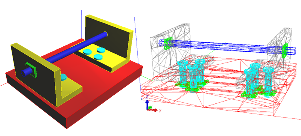
This is a sample program for the STEP Faceting library. It creates meshes for all geometry in the file, them prints the assembly structure with the positioning and mesh details. The example facets the STEP file shown below and included with the example, but you can easily change it to take any file from the command line.
The program the assembly structure and summary information about and each mesh. Set the PRINT_ALL_TRIANGLES flag at the top of the program if you would like a list of coordinates for each triangle transformed into the proper place in the assembly. In particular, if you look at the meshes for the BOLT, you can see how it is used at six different locations in the assembly.
Since this code touches all of the facets and transforms them with any assembly placements, you can adapt this code as needed to feed a display system or some other application instead of printing. In particular, the print_mesh_details() function shows how to get to each triangle in the mesh.
This code creates the meshes in parallel. The stixmesh_worker_render_design() registers all of the different solids in the file with worker threads, then the rose_mesh_worker_wait_all() function blocks until all of the faceting is finished. If you don't need a mesh for everything, the stixmesh_worker_render() function can be used to facet a particular solid or face.